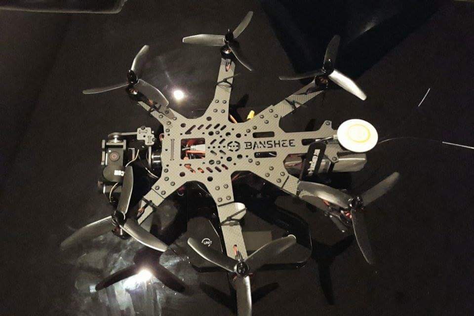
I love my Vampire hexicopter. It’s been an awesome airframe, extremely reliable, it looks awesome, and it gets fantastic video.
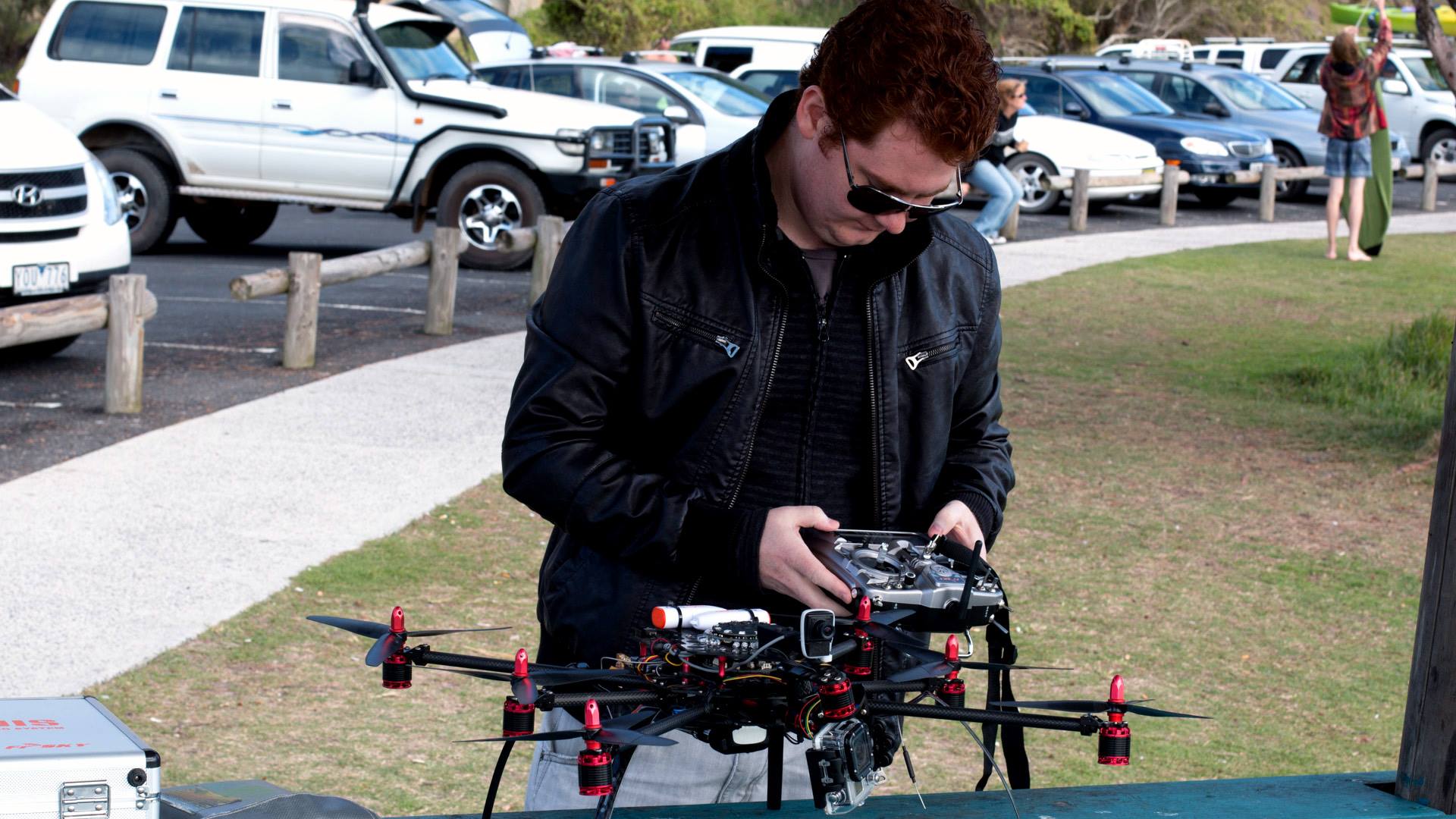
It’s main drawbacks are it’s size and it’s flight time. The Vampire takes up most of my car boot, and it’s too big to take on a plane unless you invest in an $800 flight case and take all the props off. The flight time is limited to around 7 minutes, maybe 8 if you push your batteries hard.
This made me start looking into alternatives …
I looked into a few options, including the Blackout Spider Hex, and the Quadzombies Hexi 350.
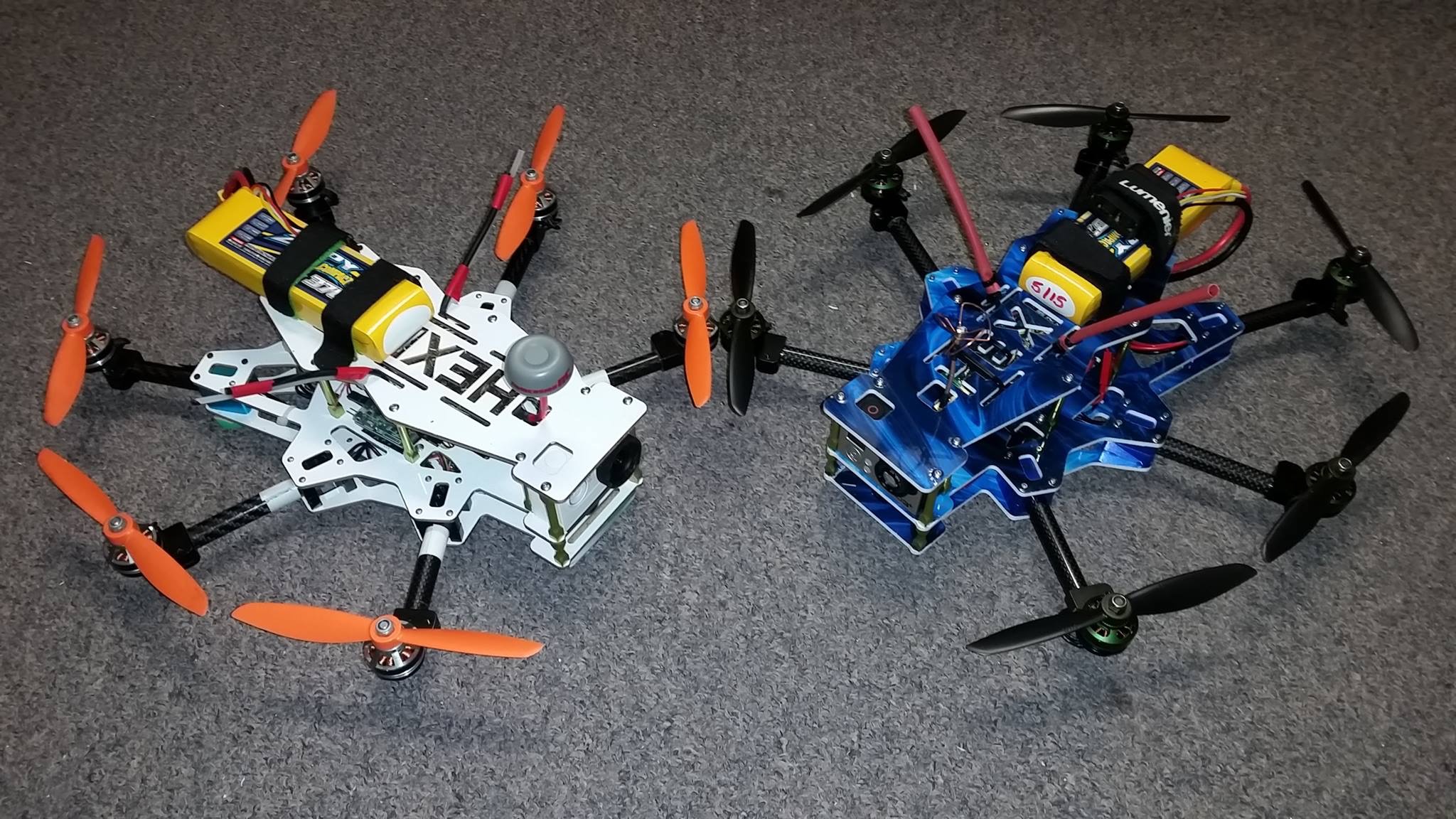
While these are both great airframes, I didn’t like that they aren’t symmetrical, and neither of them were designed for a gimbal. The closest thing is the Banshee Mini Hex designed by Ward Paterson, but this was still in development when I started my project.
I felt that I could design my own airframe that would meet my needs, which are as follows:
- Small enough for a standard flight case – around 350mm wide
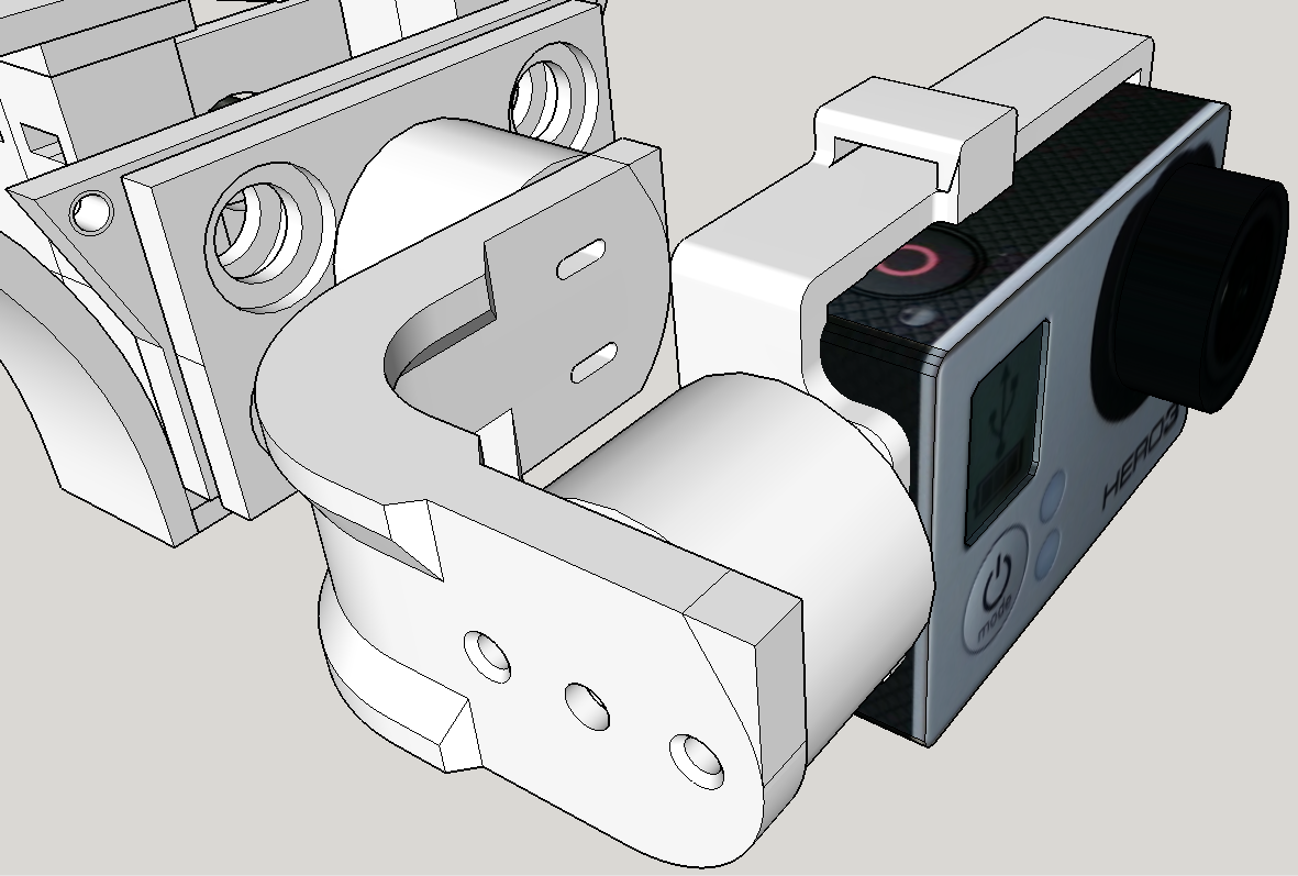
- Able to carry a gimbal and gopro for stabilized video
- Able to fit a full size flight controller – APM Pixhawk
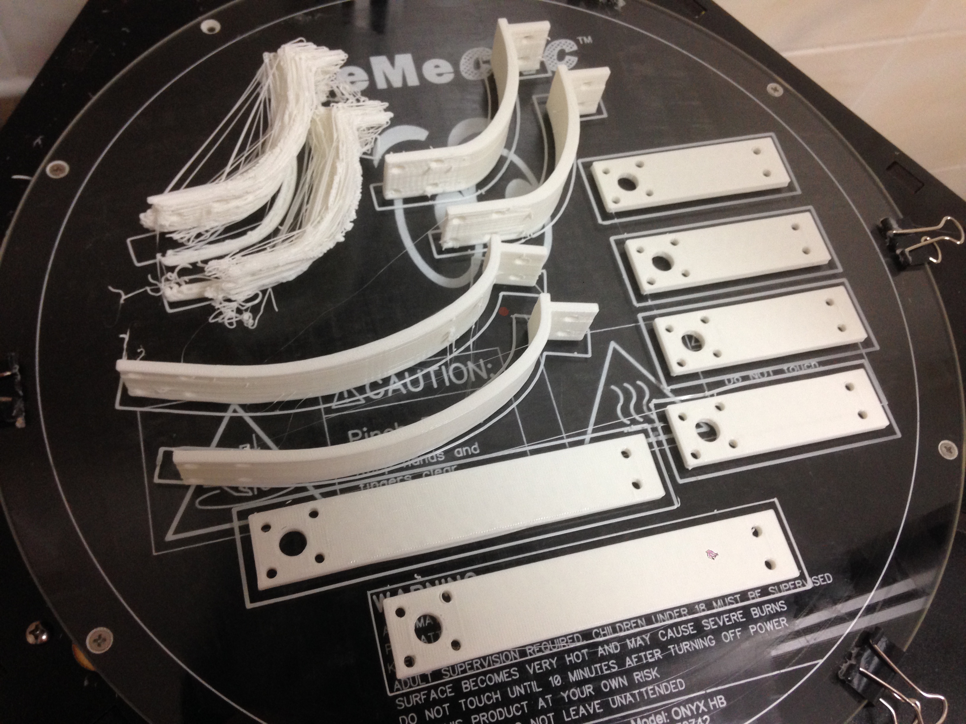
- Able to be fully or mostly 3D printed
The main challenges I identified were centered around weight and strength, as I wasn’t sure if the PLA plastic that I would be printing would be strong enough for an airframe. I was also concerned that in order to make it strong enough, it would result in far more weight than a similar carbon fiber frame.
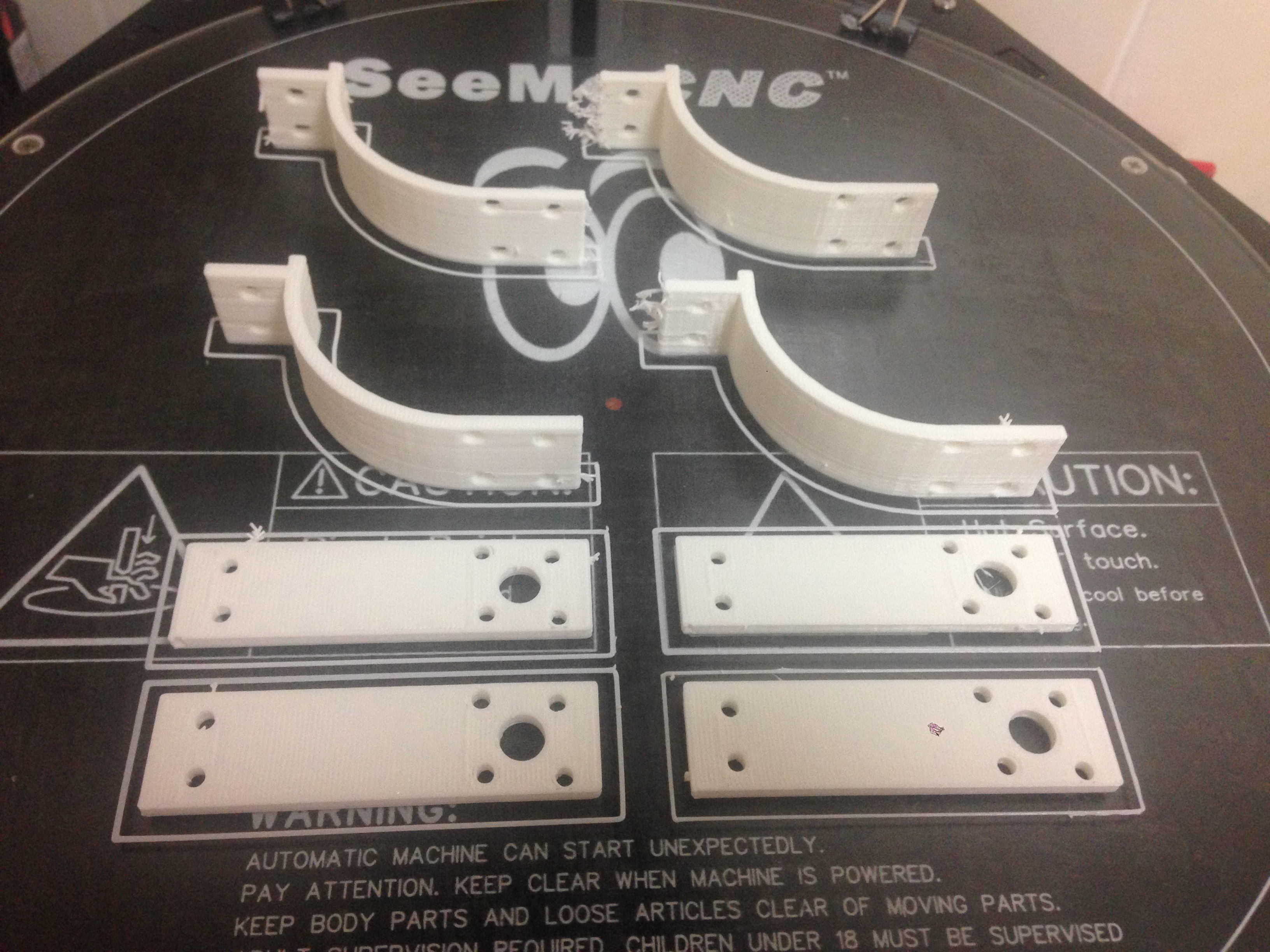
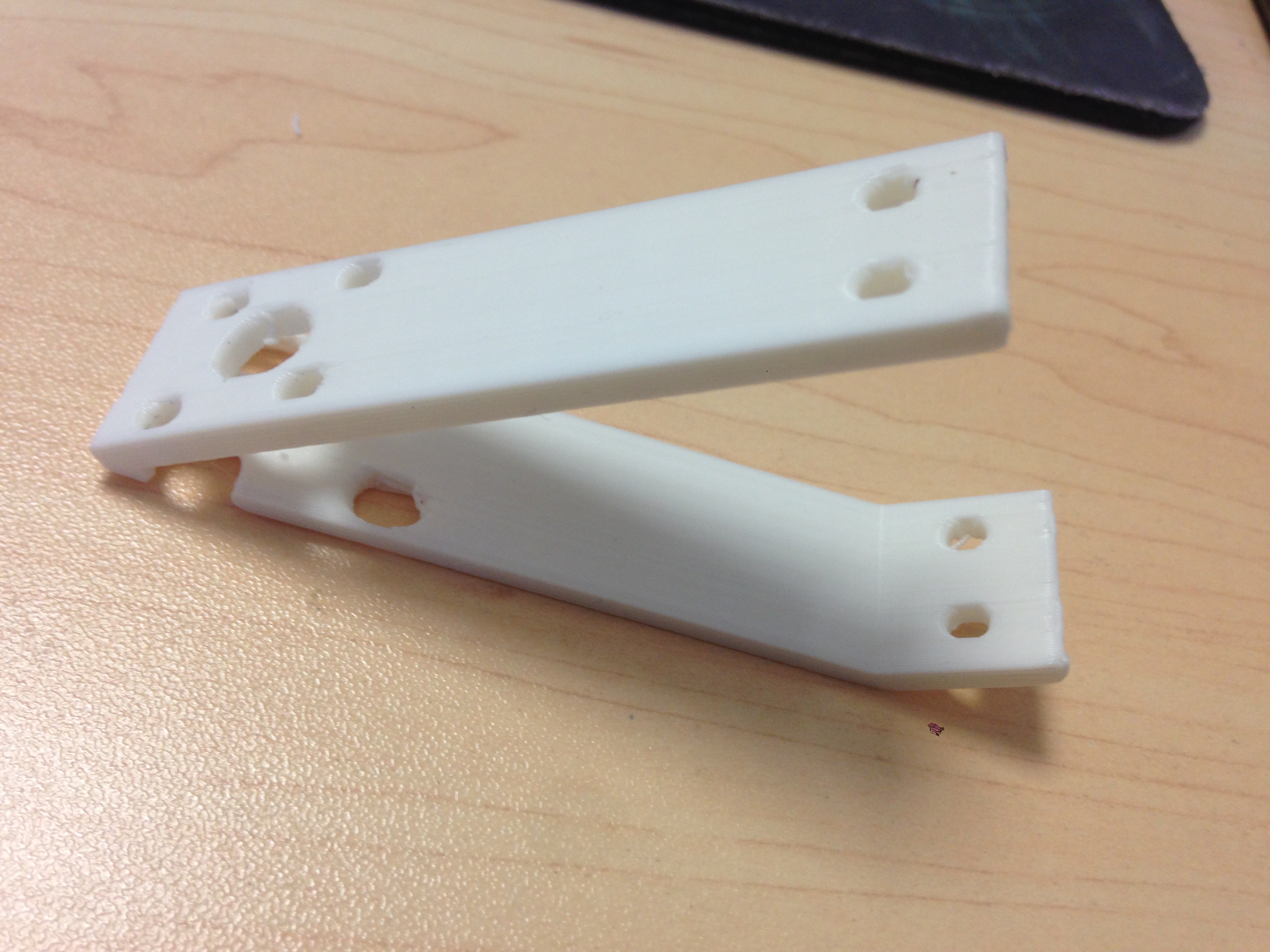
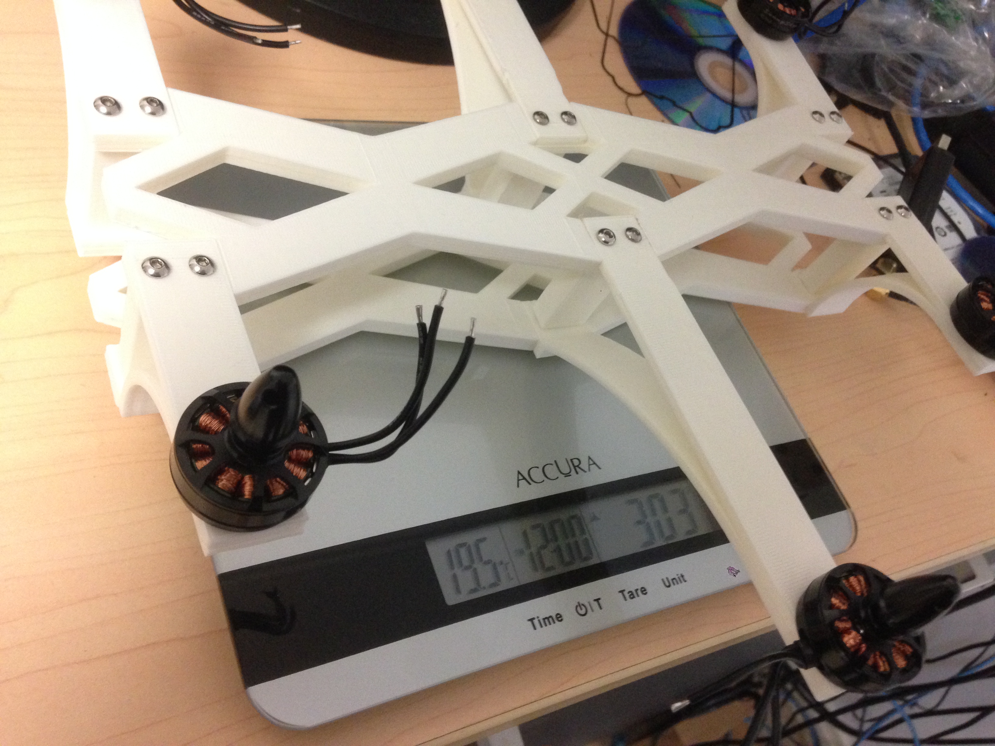
To determine if the PLA plastic would be strong enough, I printed a few different styles of motor arm, and compared their weight and amount of flex with carbon fiber.
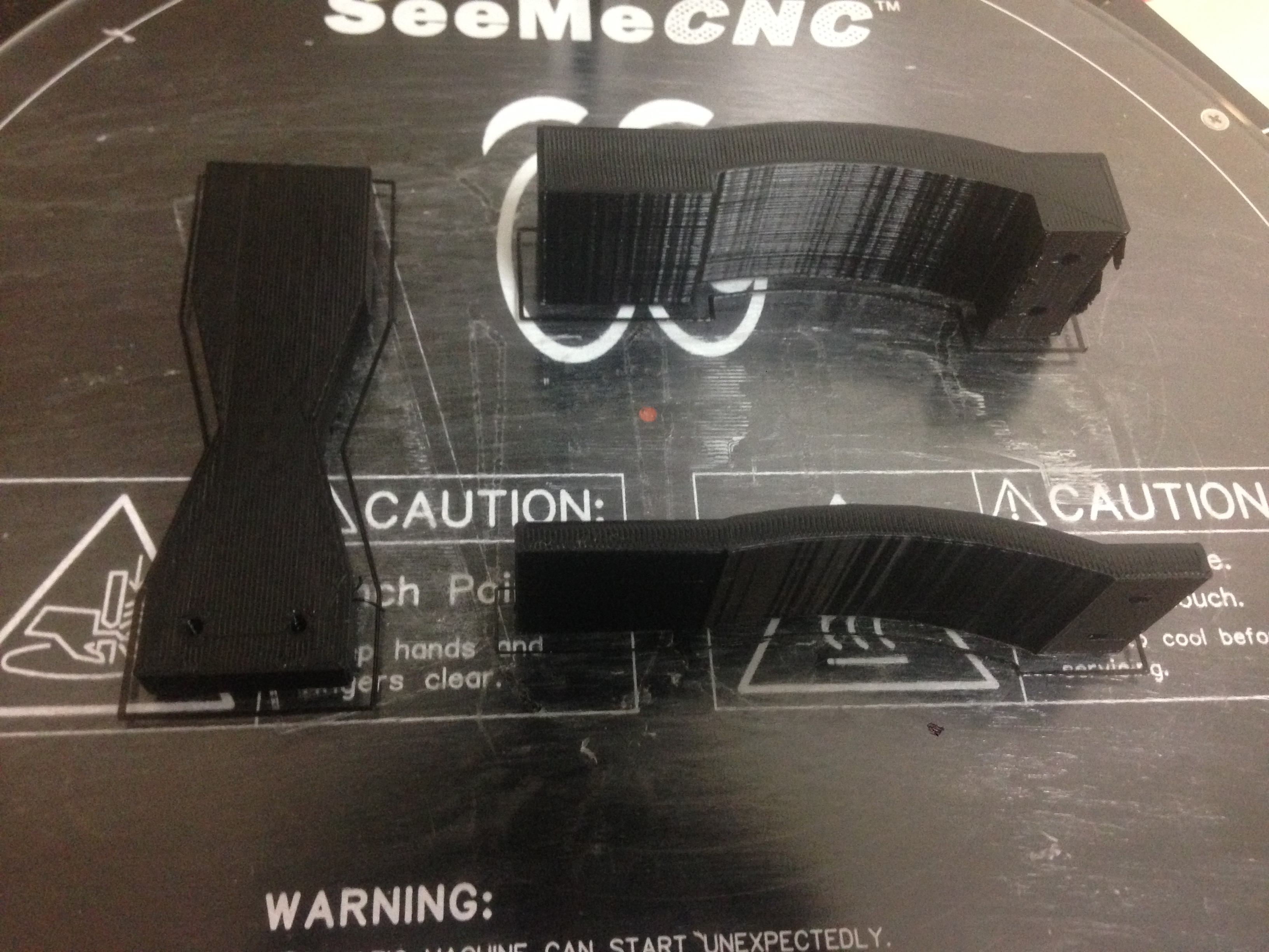
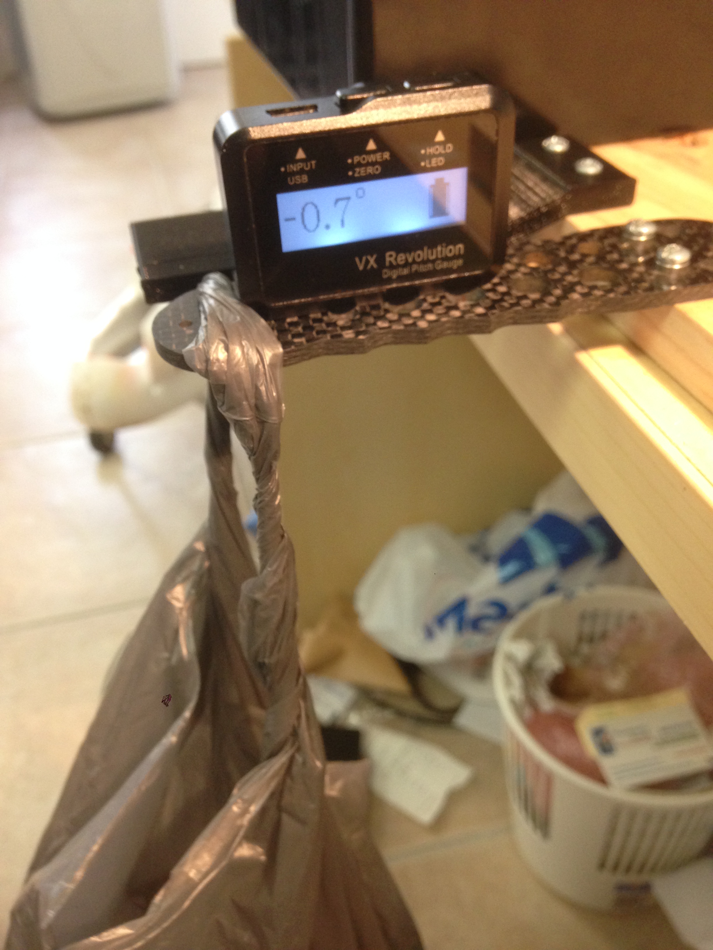
I found that the thicker 3D printed boom from the 1st picture deflected only 0.3 degrees more than the carbon fiber boom under 1KG of weight. It wasn’t super scientific, but it at least gave me peace of mind that my plan was possible.
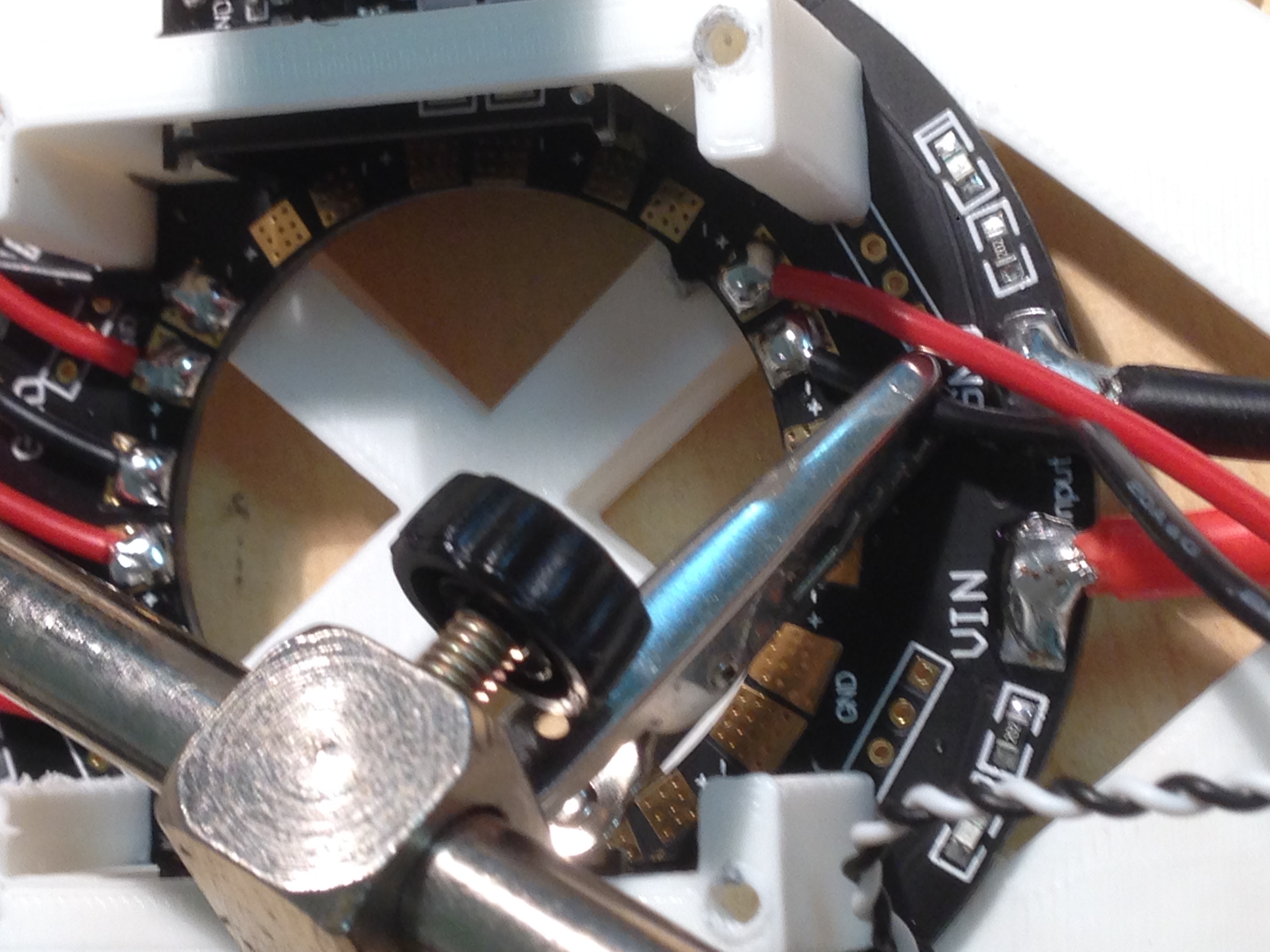
In order to determine how I would design the airframe, I needed to work out the total weight of my airframe, and balance this against the amount of thrust generated by my motors. I started a giant excel sheet, wherein I detailed the gram-weight of every component to be fitted to the airframe.
I decided on the Sunnysky X2204S motors, as these motors are extremely popular, and there was a wealth of information posted by other pilots with a variety of propeller and battery combinations at differing throttle percentages. This gave me the information I needed to start to work out estimated flight times.
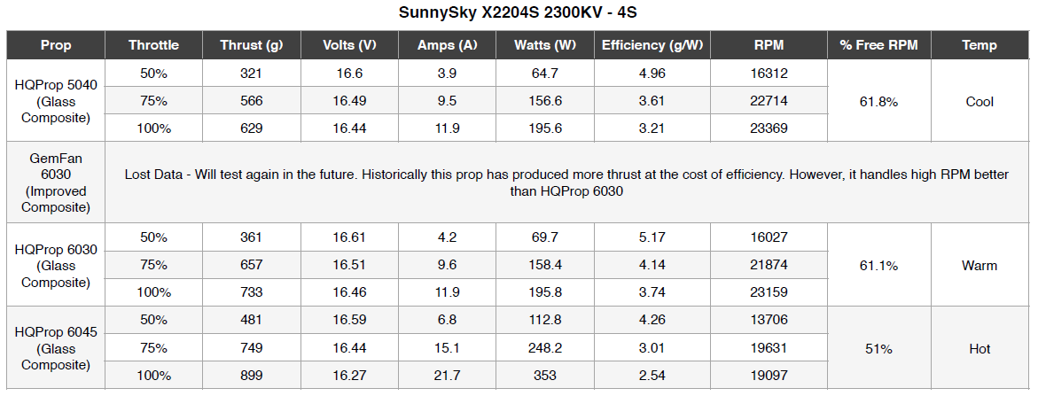
I determined that 3S batteries around 5000mah would give the best flight time, due to their low weight and high capacity. However I have a bunch of 4S 4200mah batteries left over from my Vampire, so decided to use those for my project. I estimated a flight time of 14-15 minutes with a 4S 4200mah battery.
I ordered the equipment I needed and started designing!
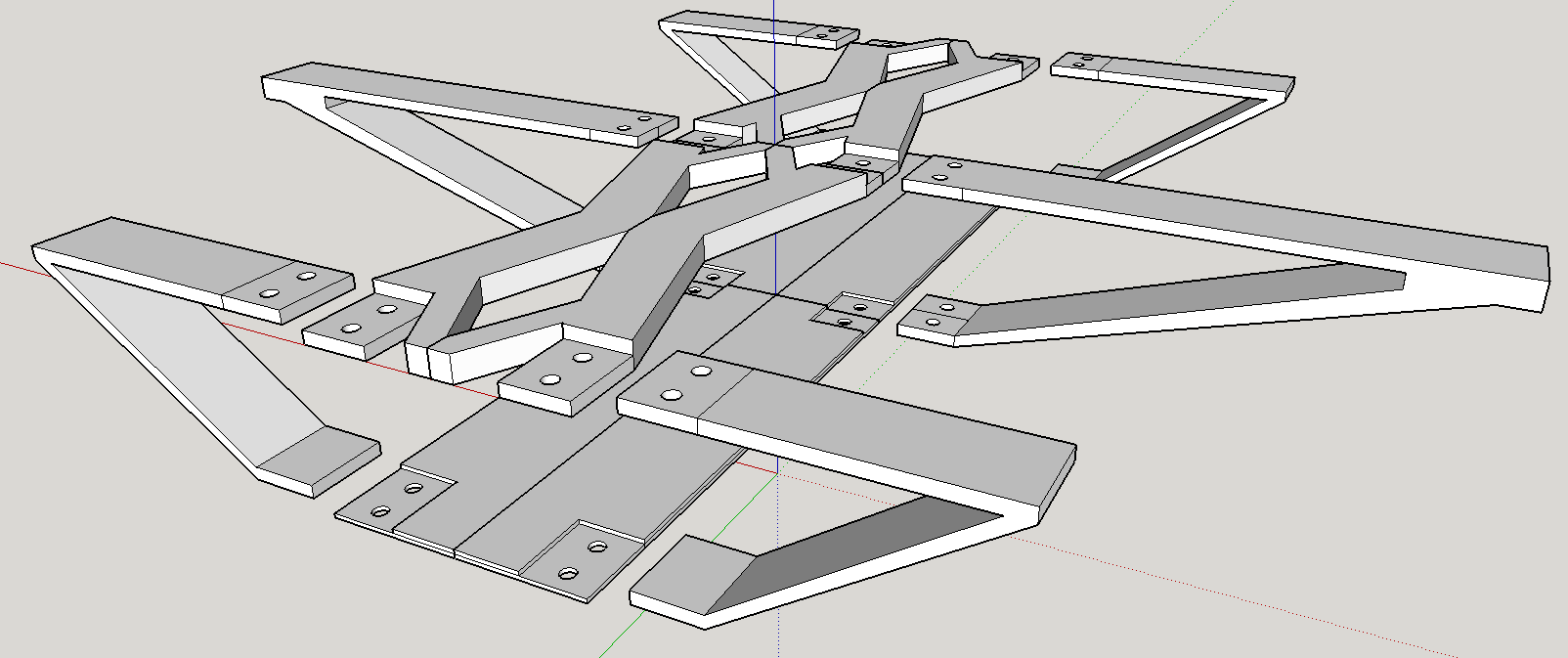
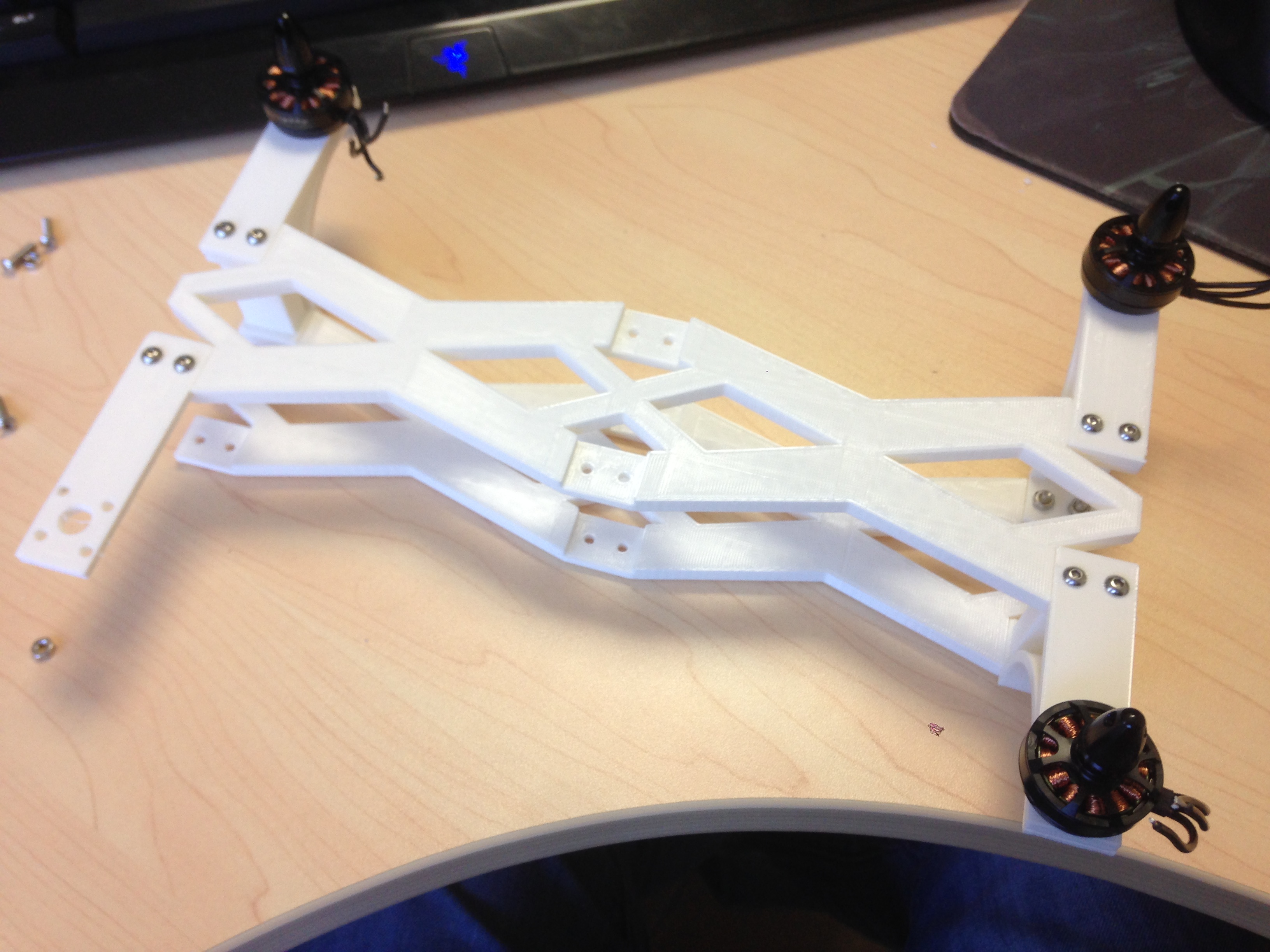
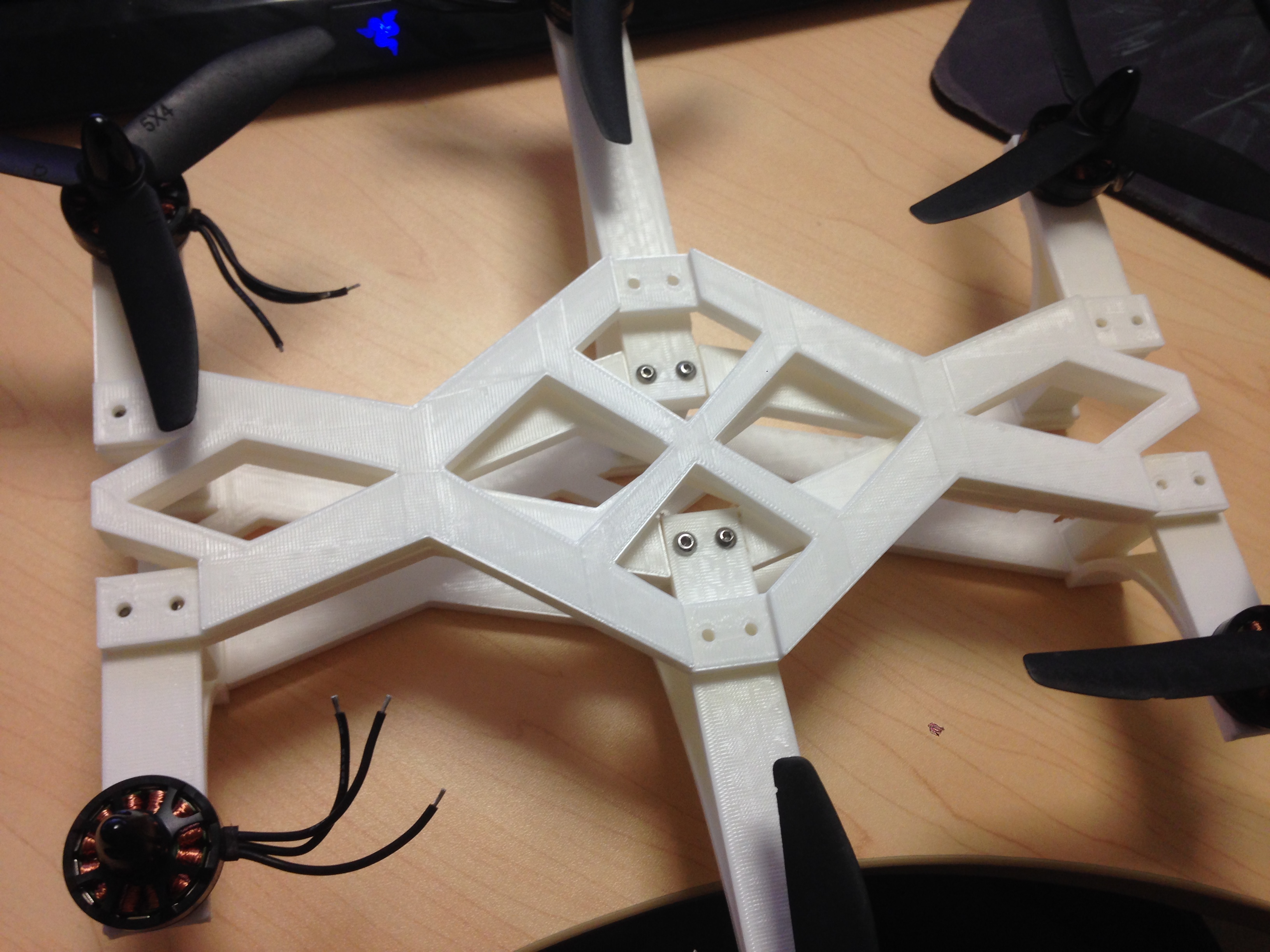
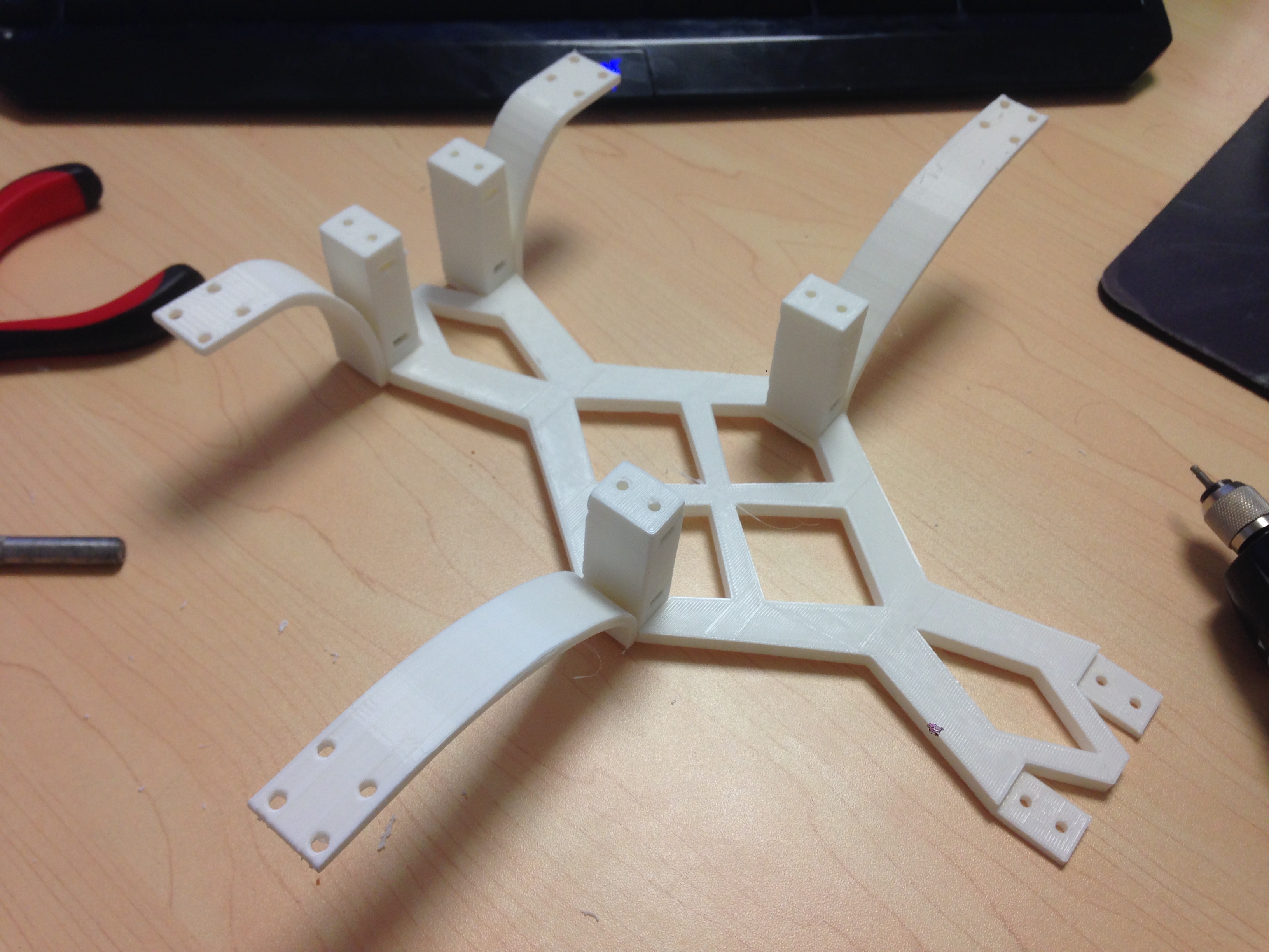
I wanted to keep the length of the booms as short as possible, as I was concerned over the amount of flex in the arms, so rather than having the arms radiate from the center, I went for a rectangular frame with different length booms. I found that having a two-part boom resulted in good strength and lightness. The lower frame plate was going to be there anyway, so we might as well use it to add strength to the arms.
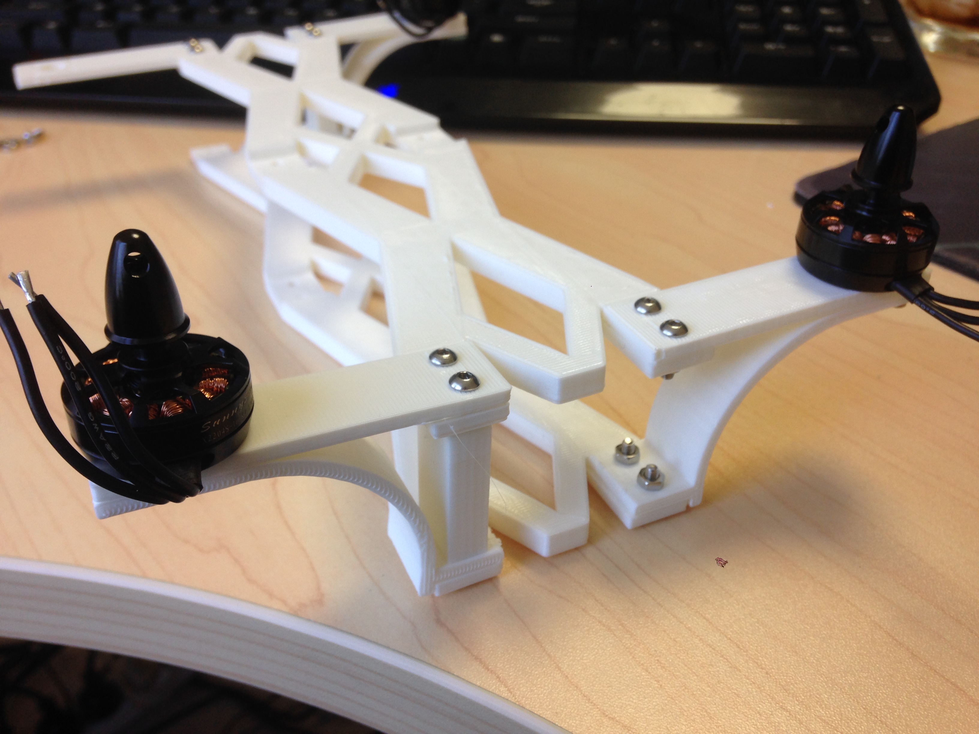
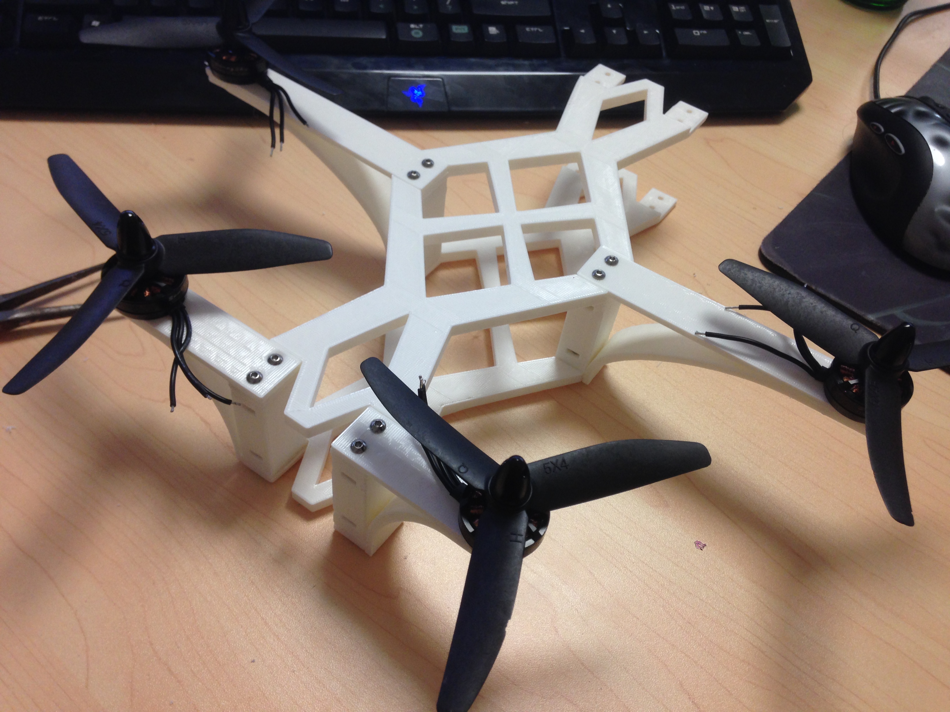
Test fitting standoffs. Originally I planned to have bolts go through the entire frame, but as the frame got thicker, I couldn’t source bolts that were long enough. Also, the motors are facing the wrong way!
I experimented with printing the arms as once piece, but this didn’t add any noticable strength, and resulted in all sorts of problems getting access to the motor bolts.

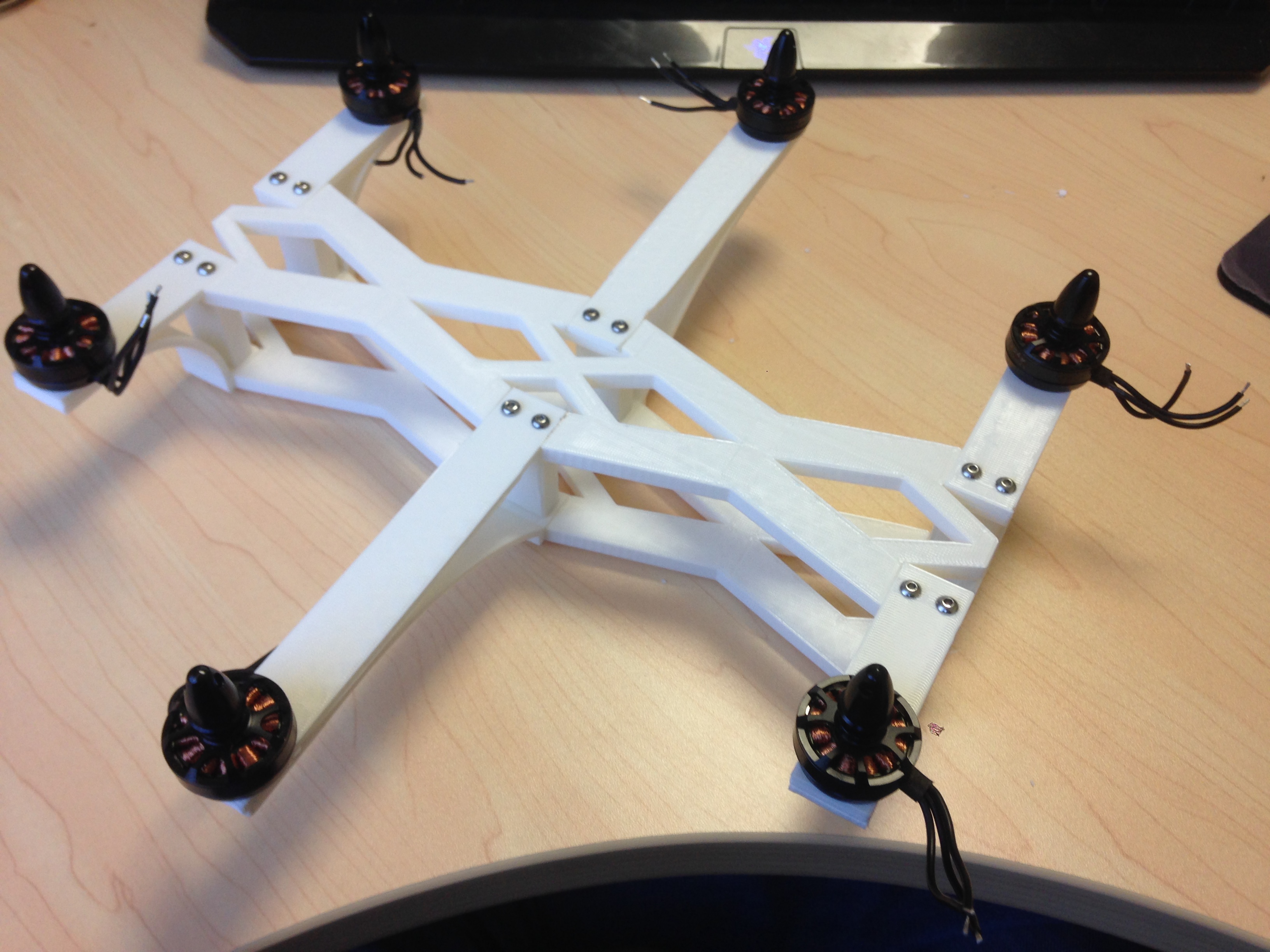
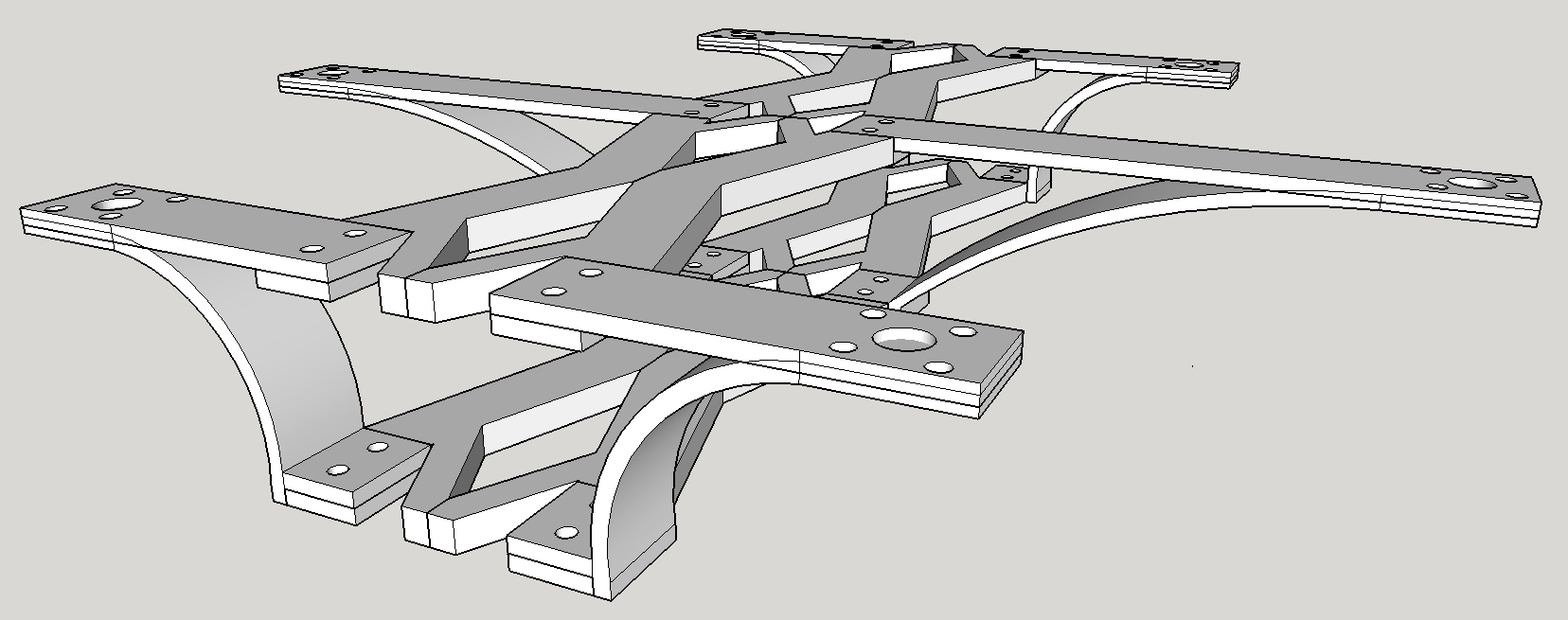
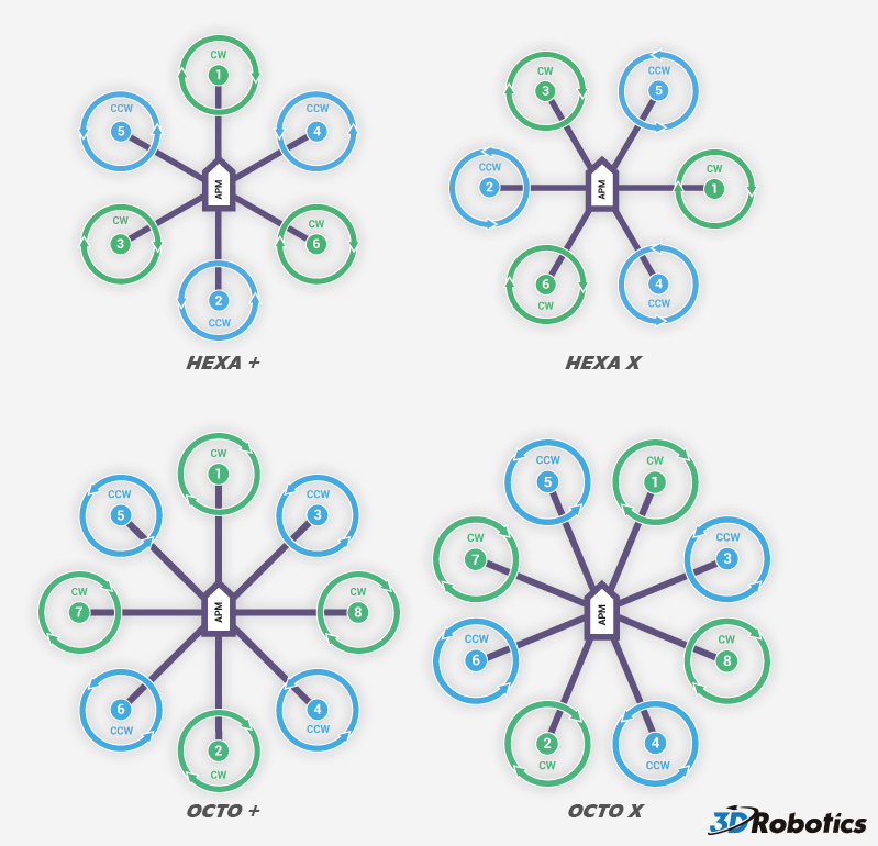
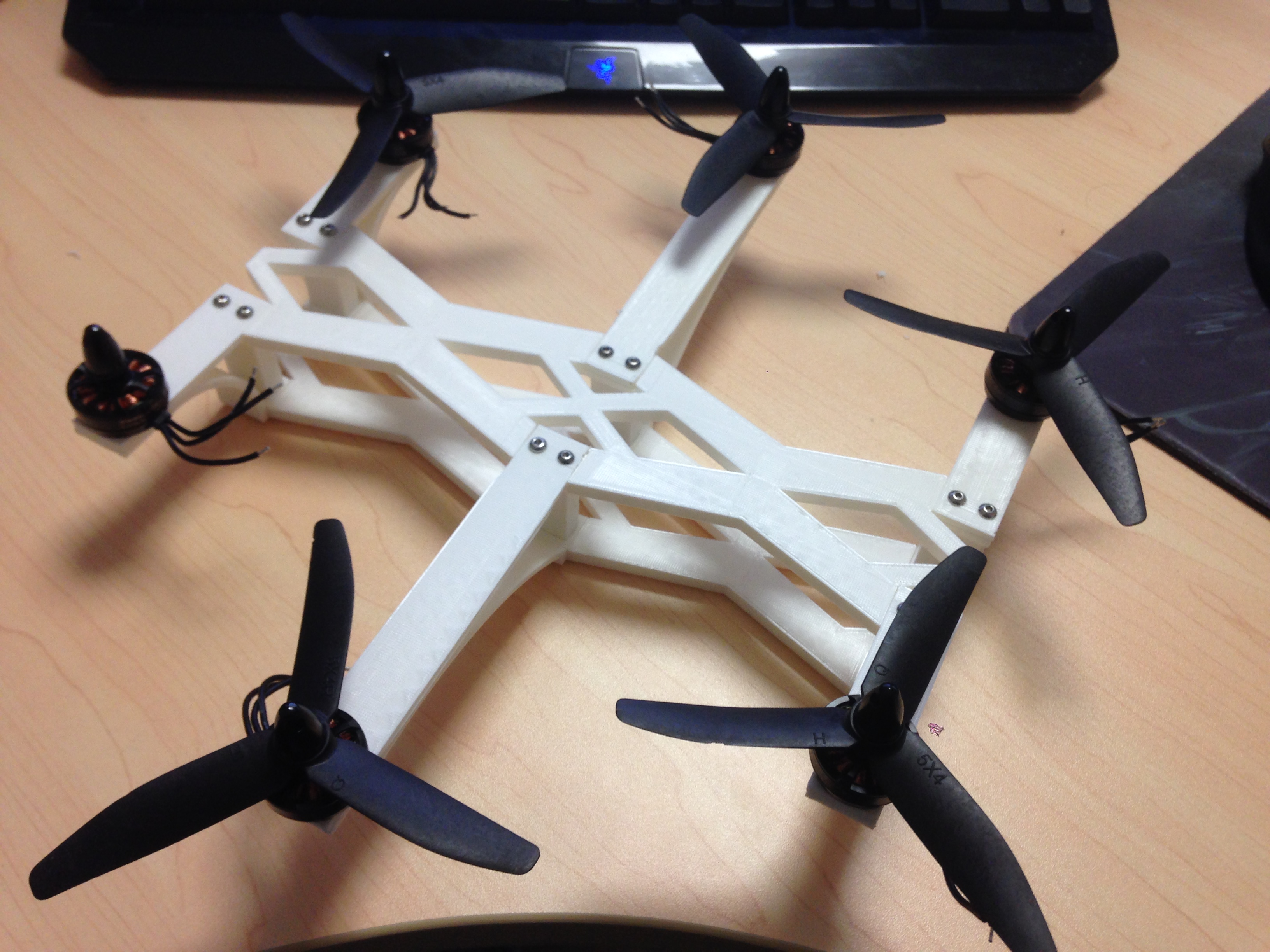
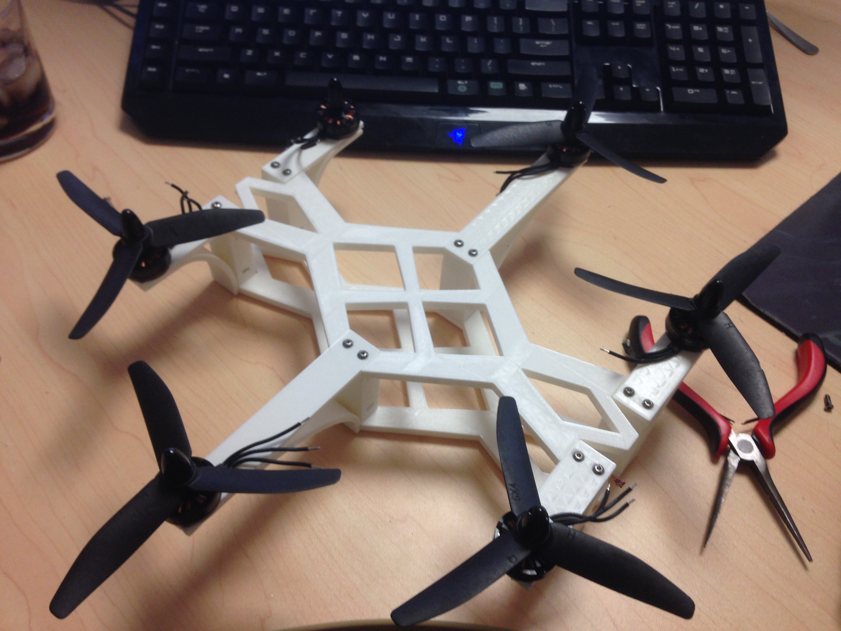
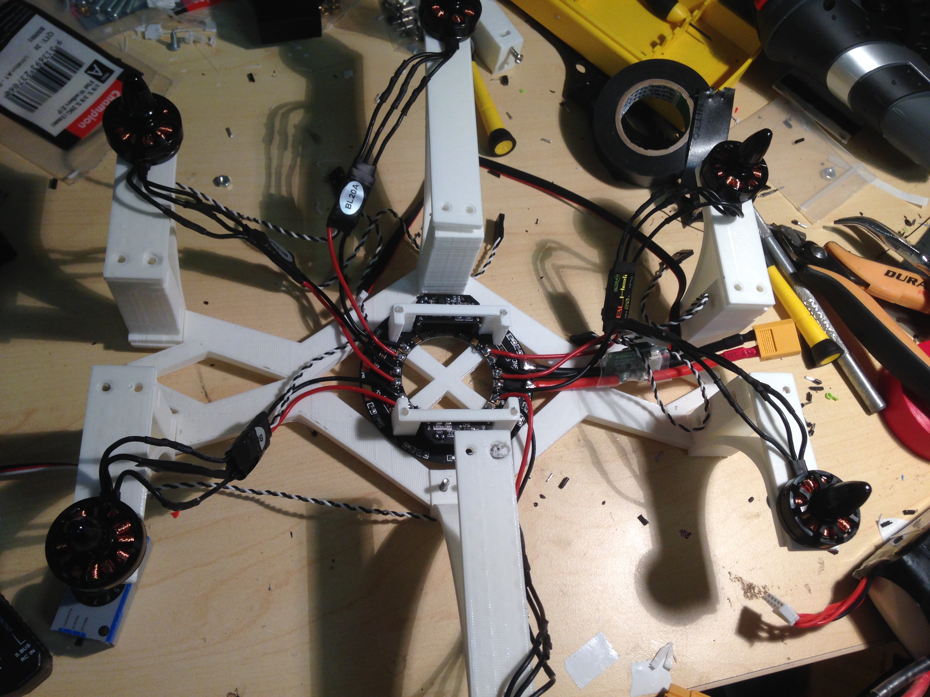
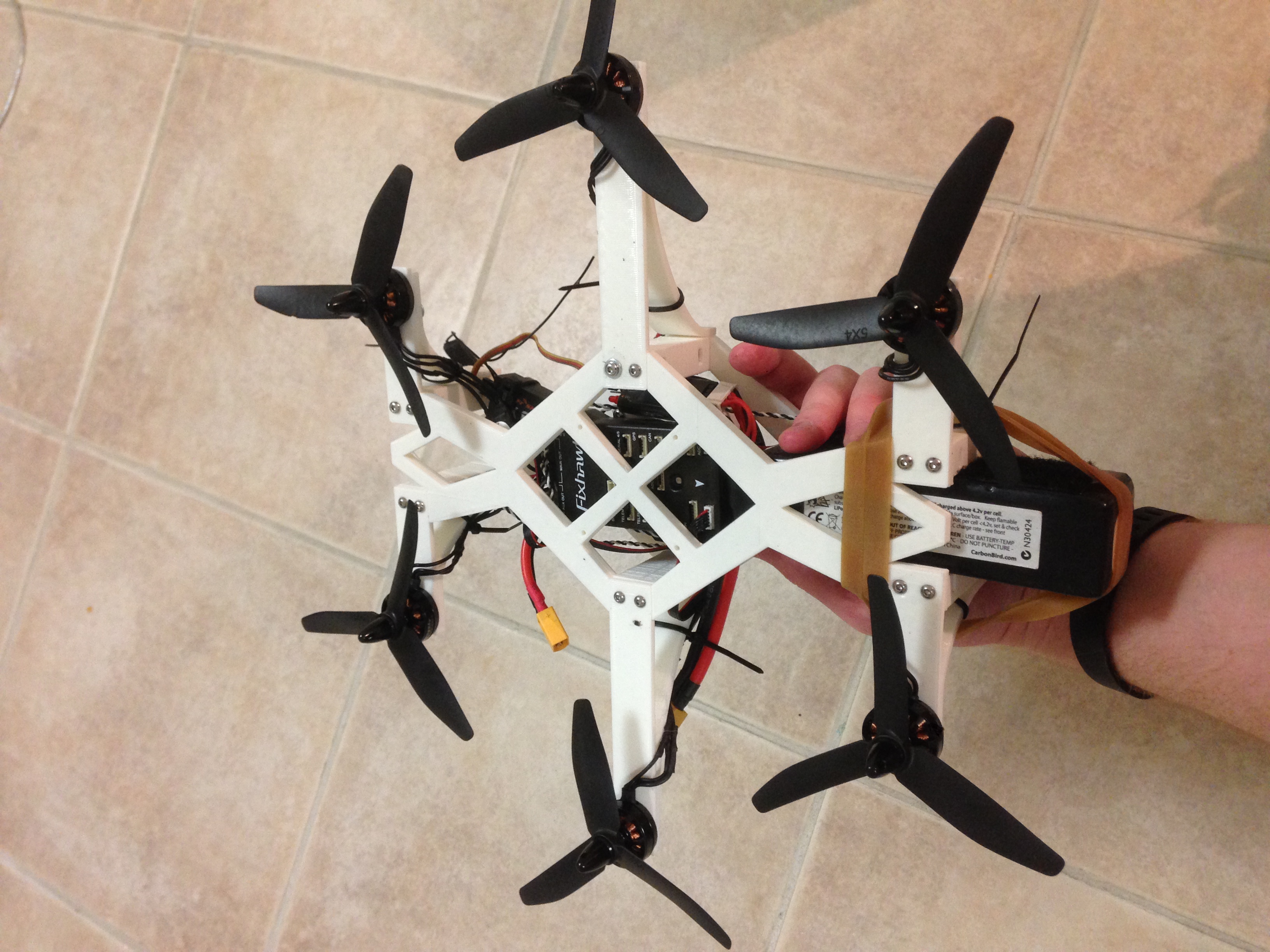
The airframe was designed to be completely symmetrical, to match the flight controller’s ‘expected layout’ perfectly.
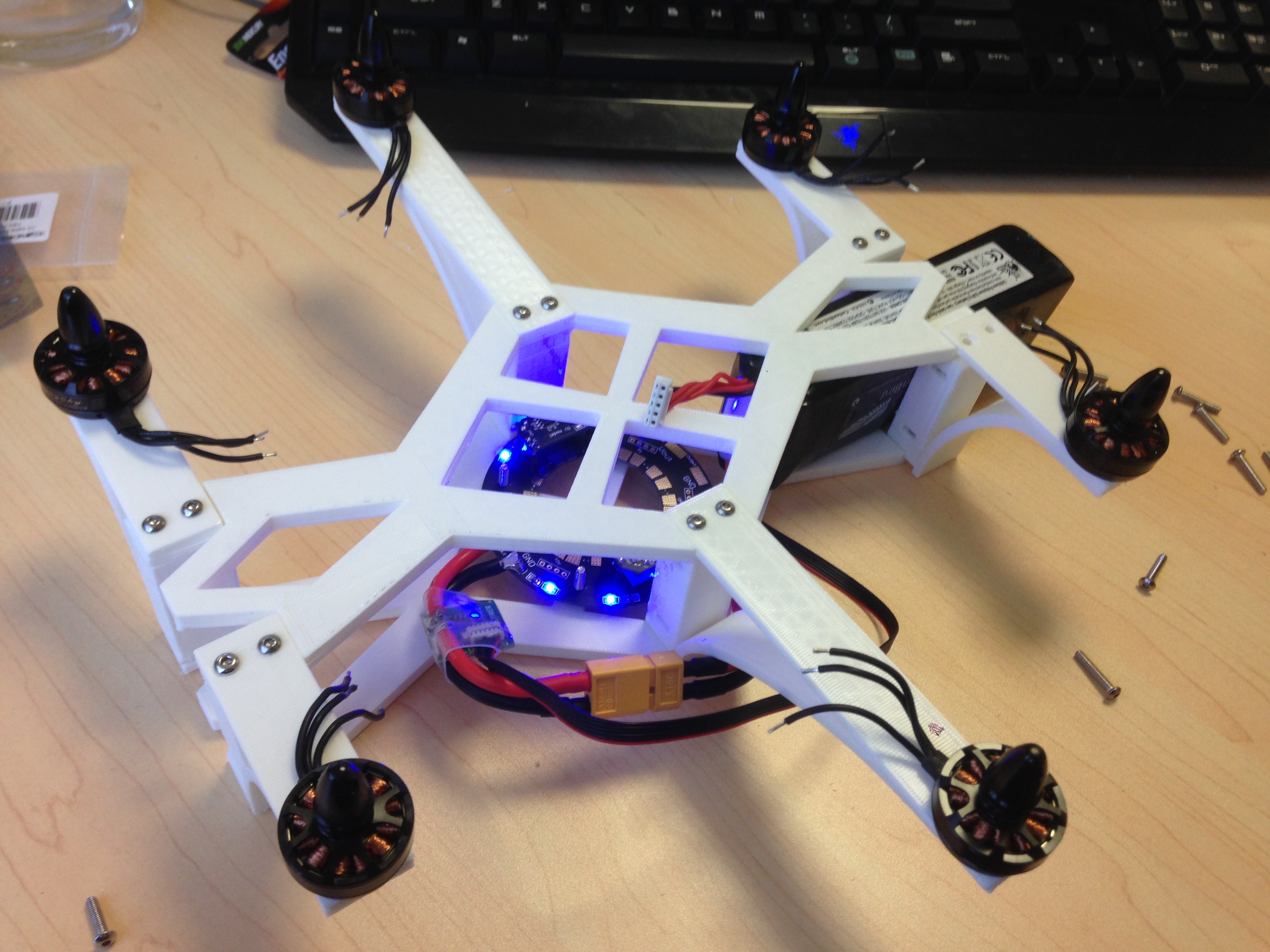
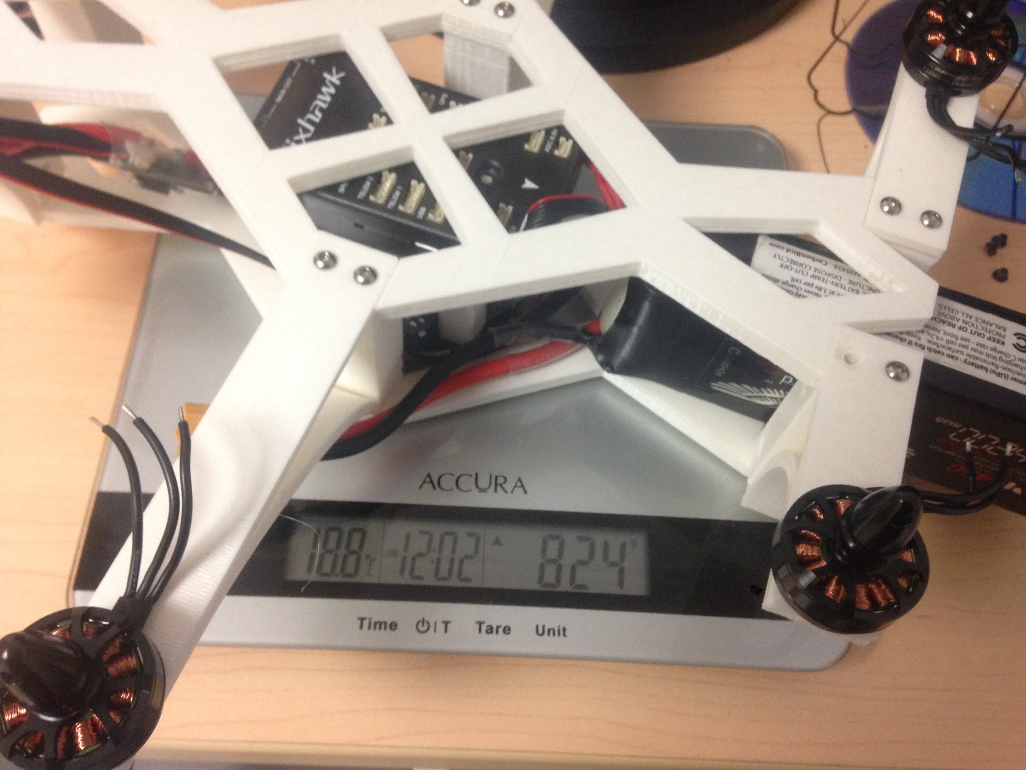
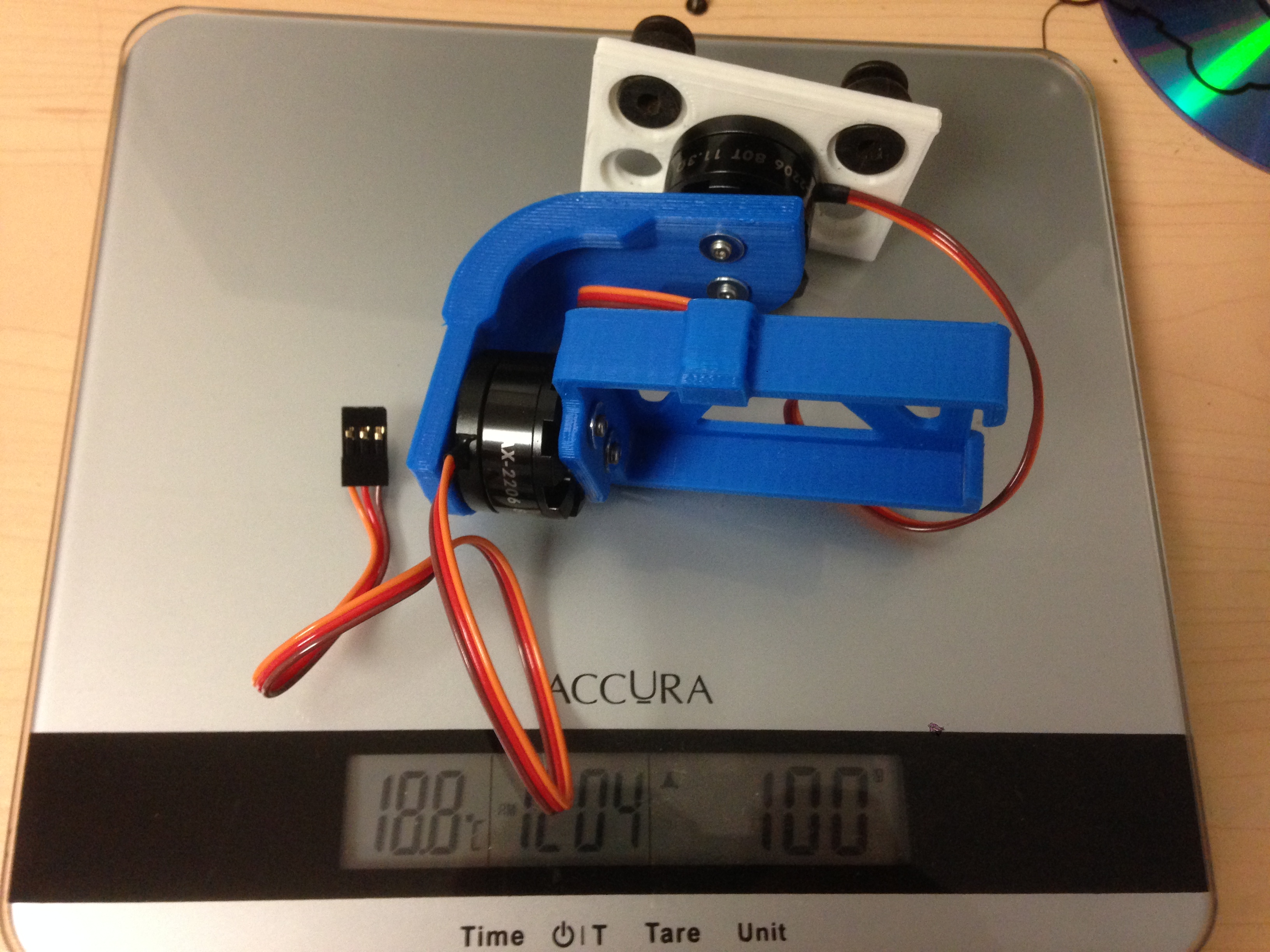
Weighing the airframe with all motors attached – not bad!
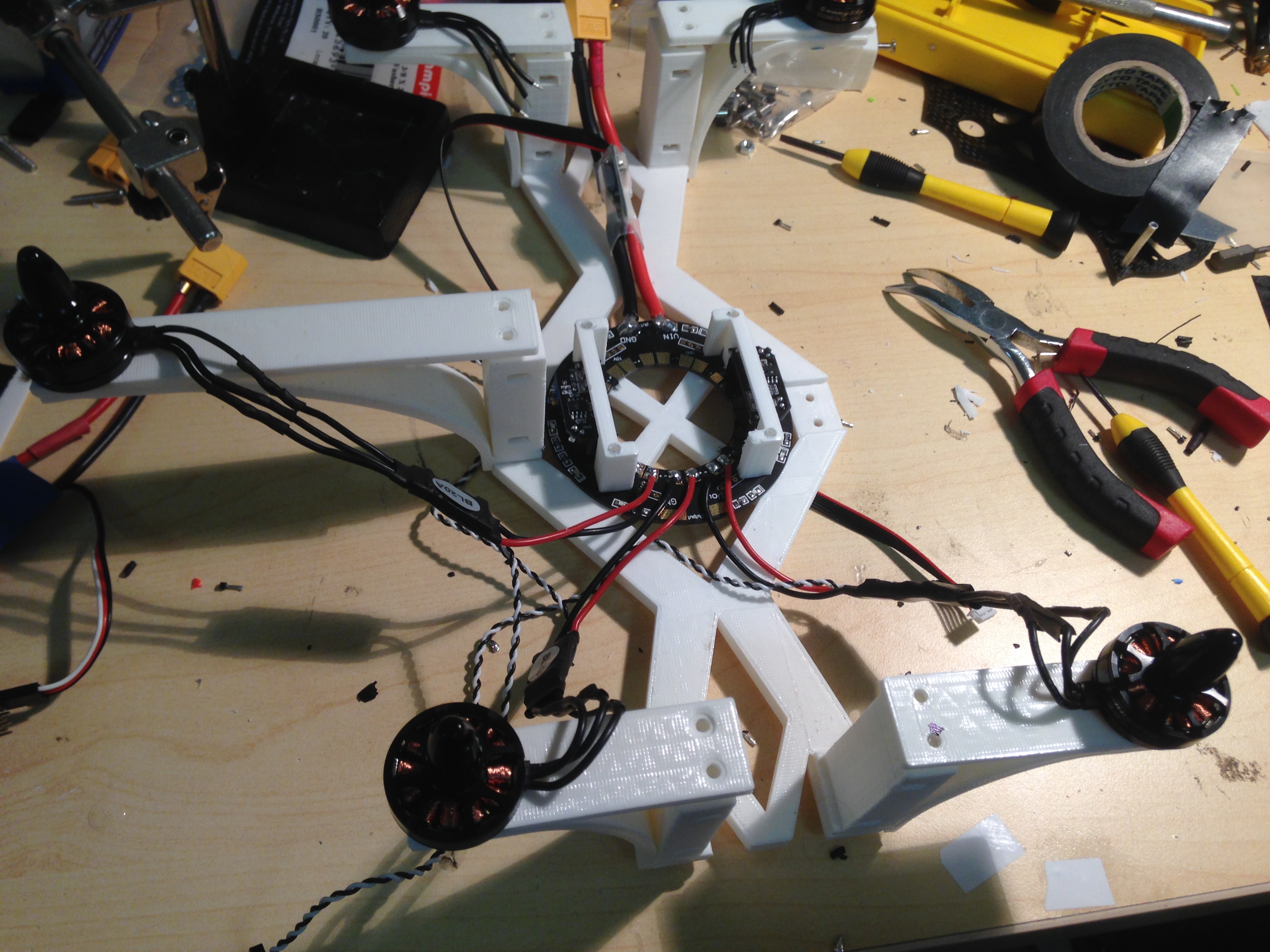
Widening the plates to make room for the power distribution board and electronics … of course this meant an entire reprint –
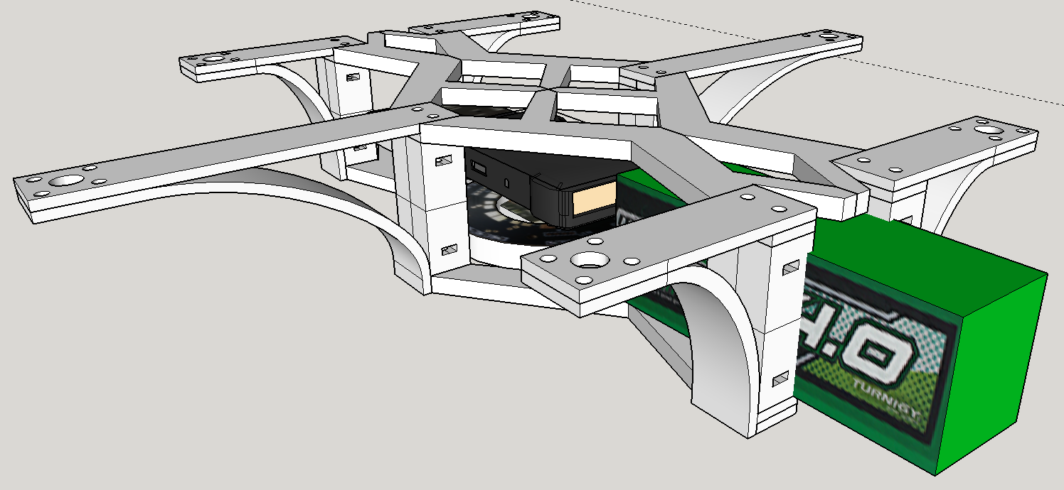
Starting to become more familiar with the 3D modelling software now … I’m modelling the electronic components so I can get all the dimensions correct.
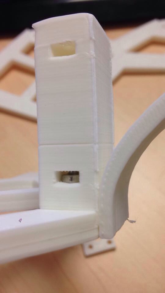
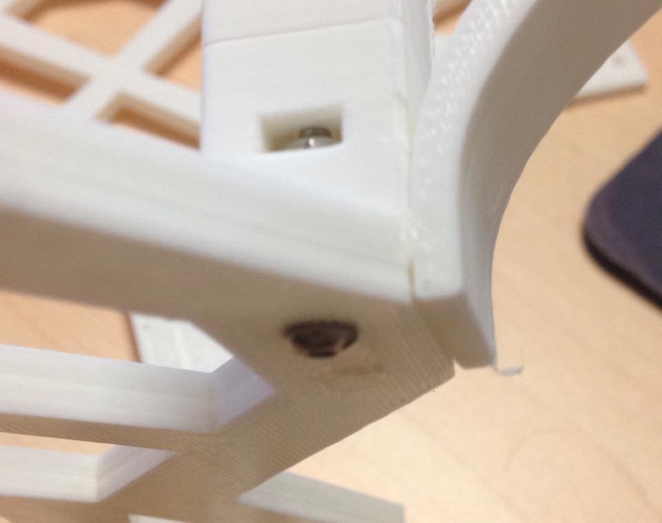
Inspired by my 3D printer build, I designed these standoffs with small nut ‘capture’ slots. You can poke the nut into the hole and the bolt then grabs and creates a very strong joint.
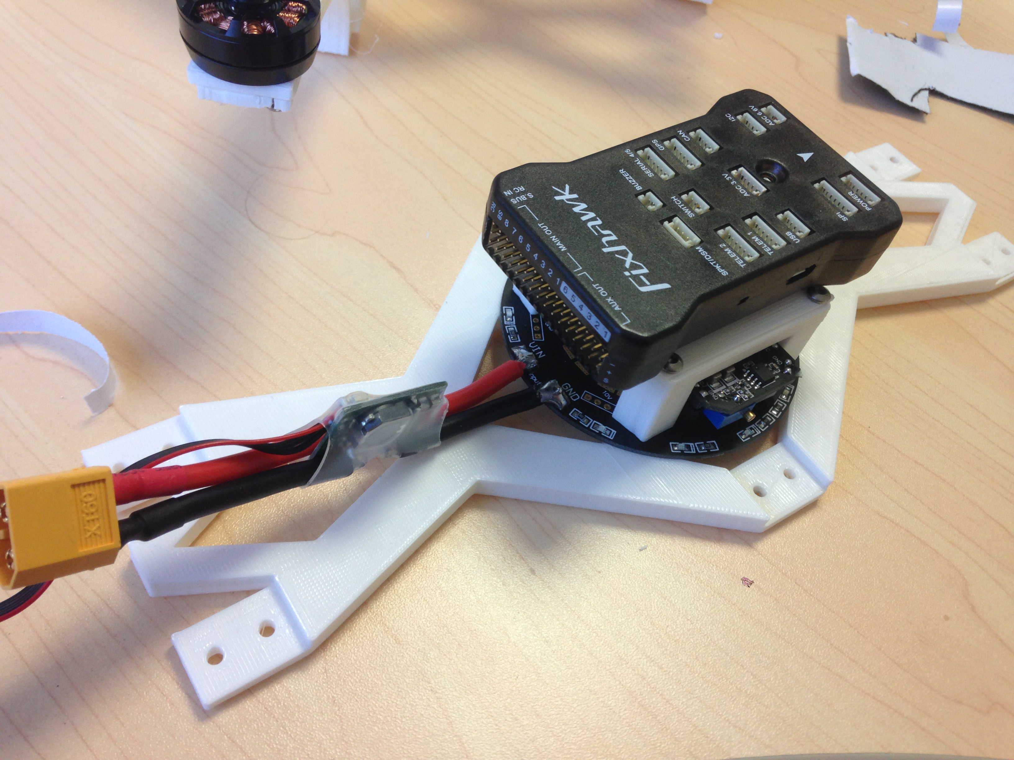
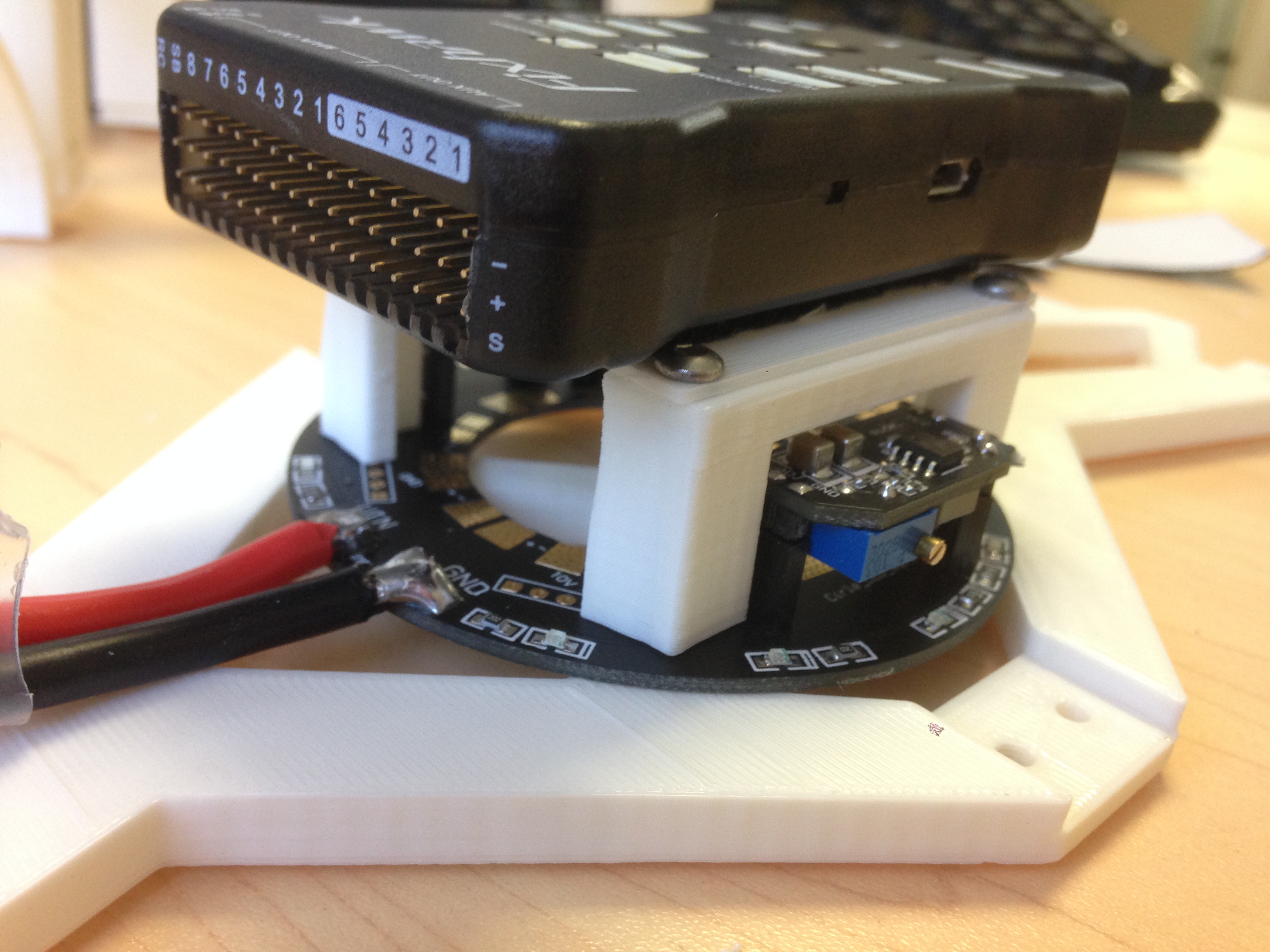
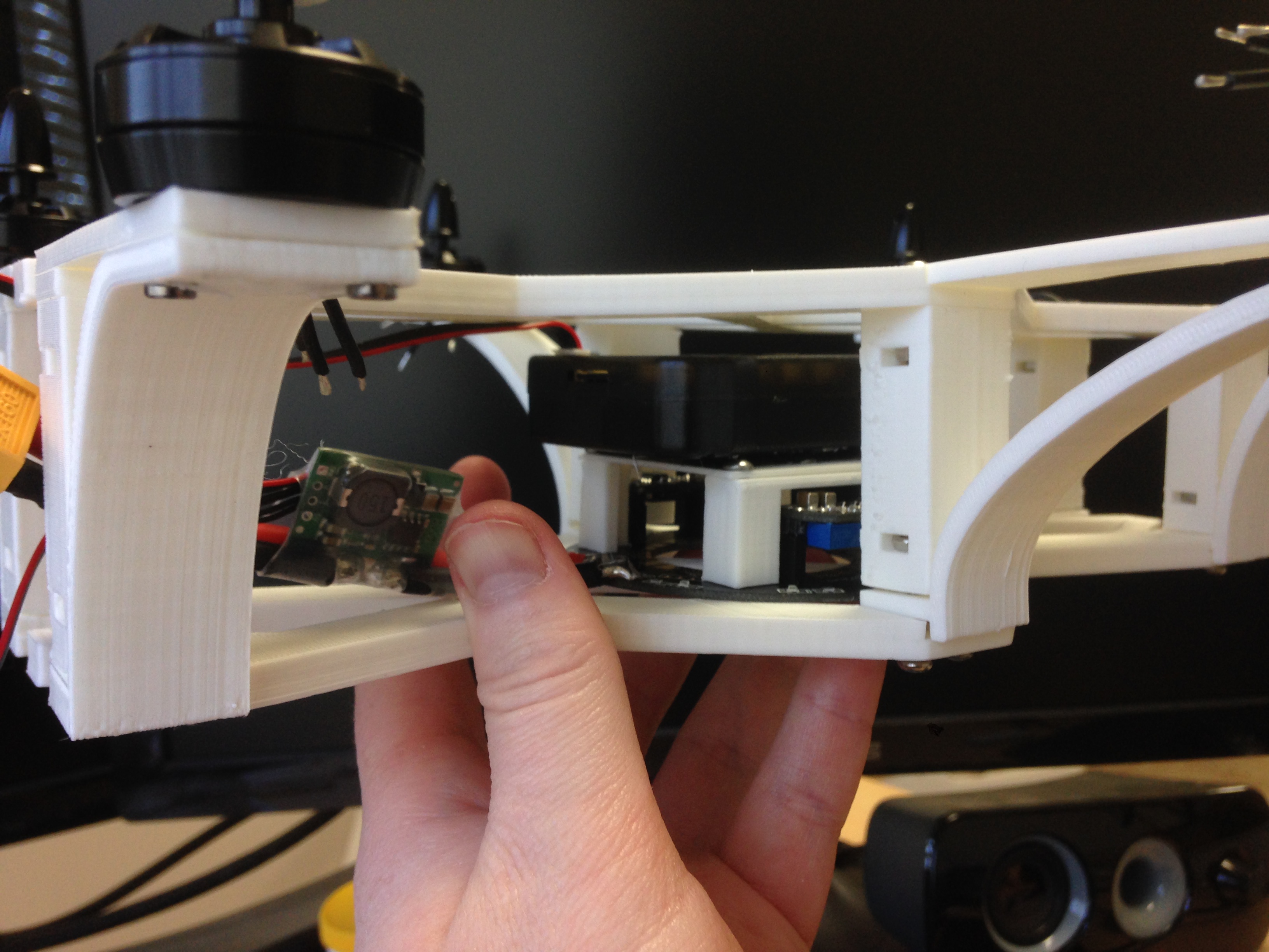
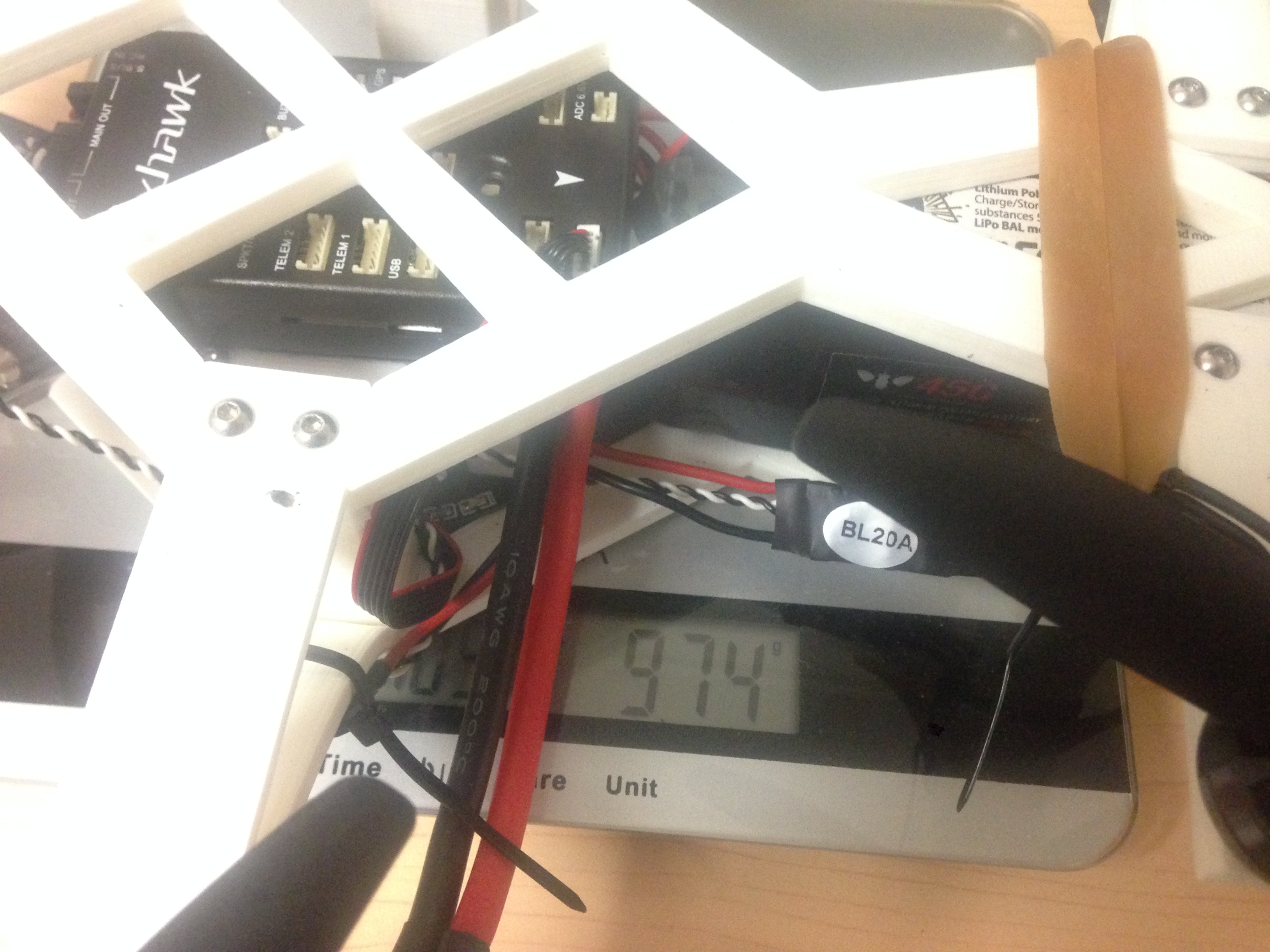
Test fitting electronics. I built this ‘stand’ for the APM, I wanted to have the flight controller as close to the plane of the motors as possible. I also realized that having the power distribution above the flight controller may introduce interference into the sensitive GPS and compass components.
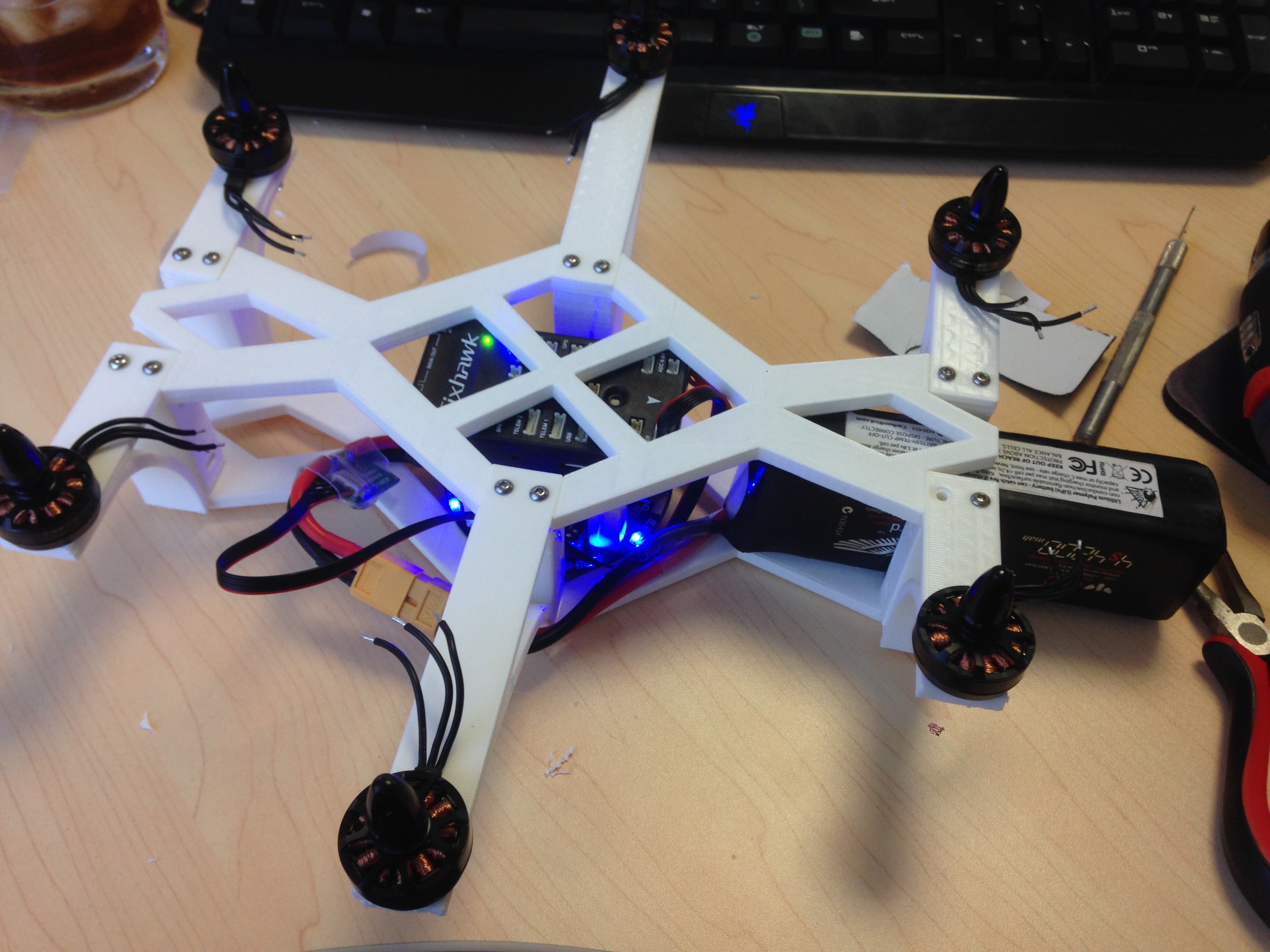
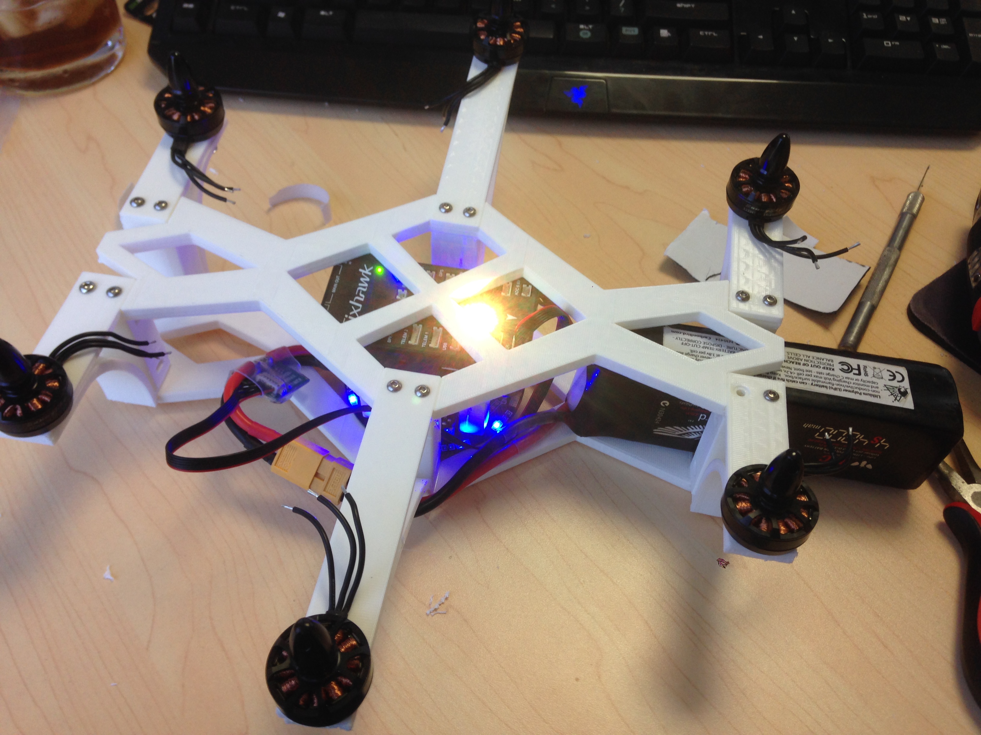
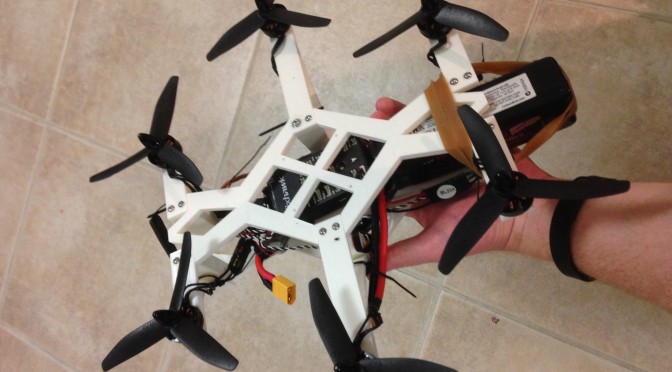
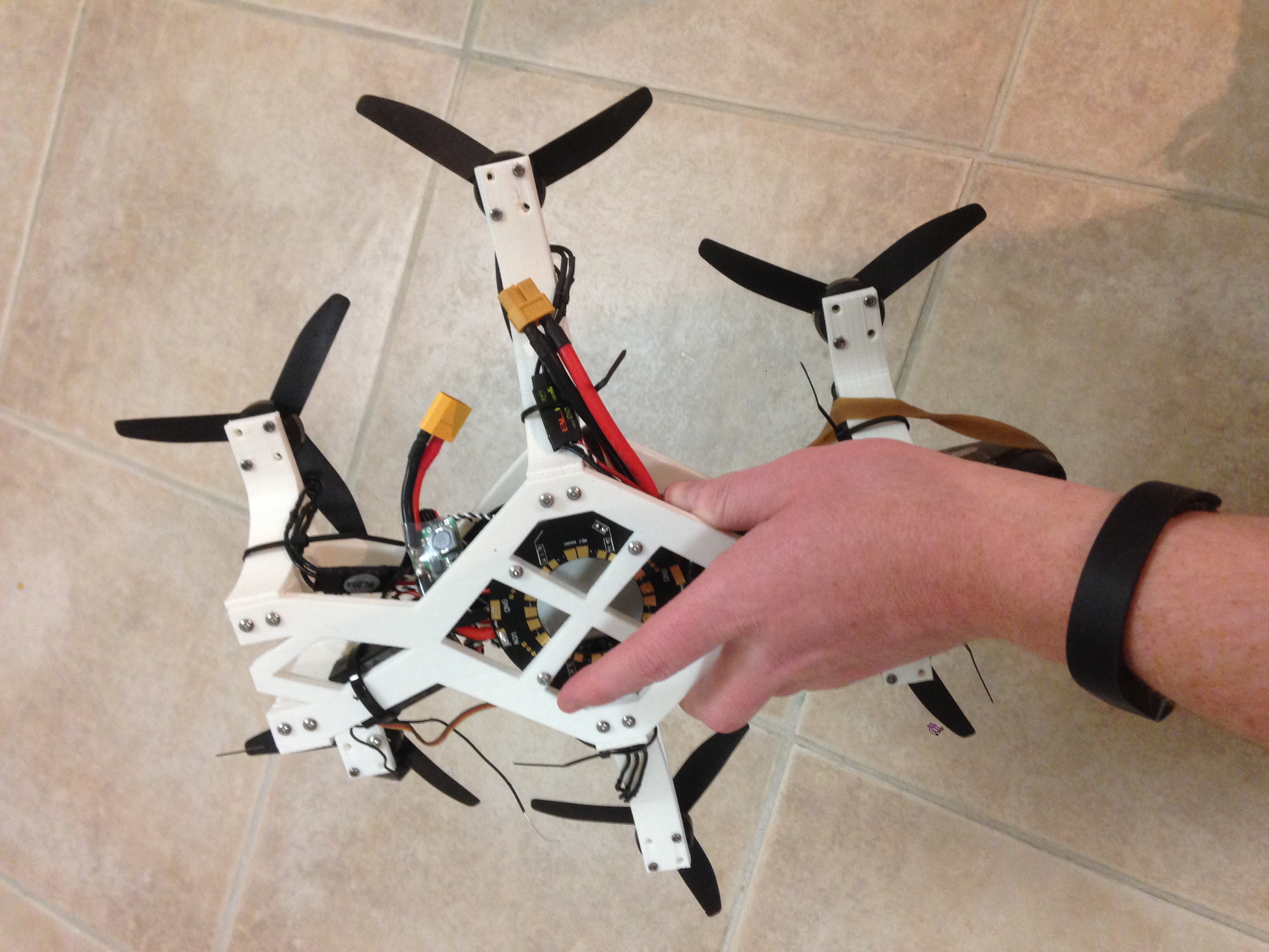
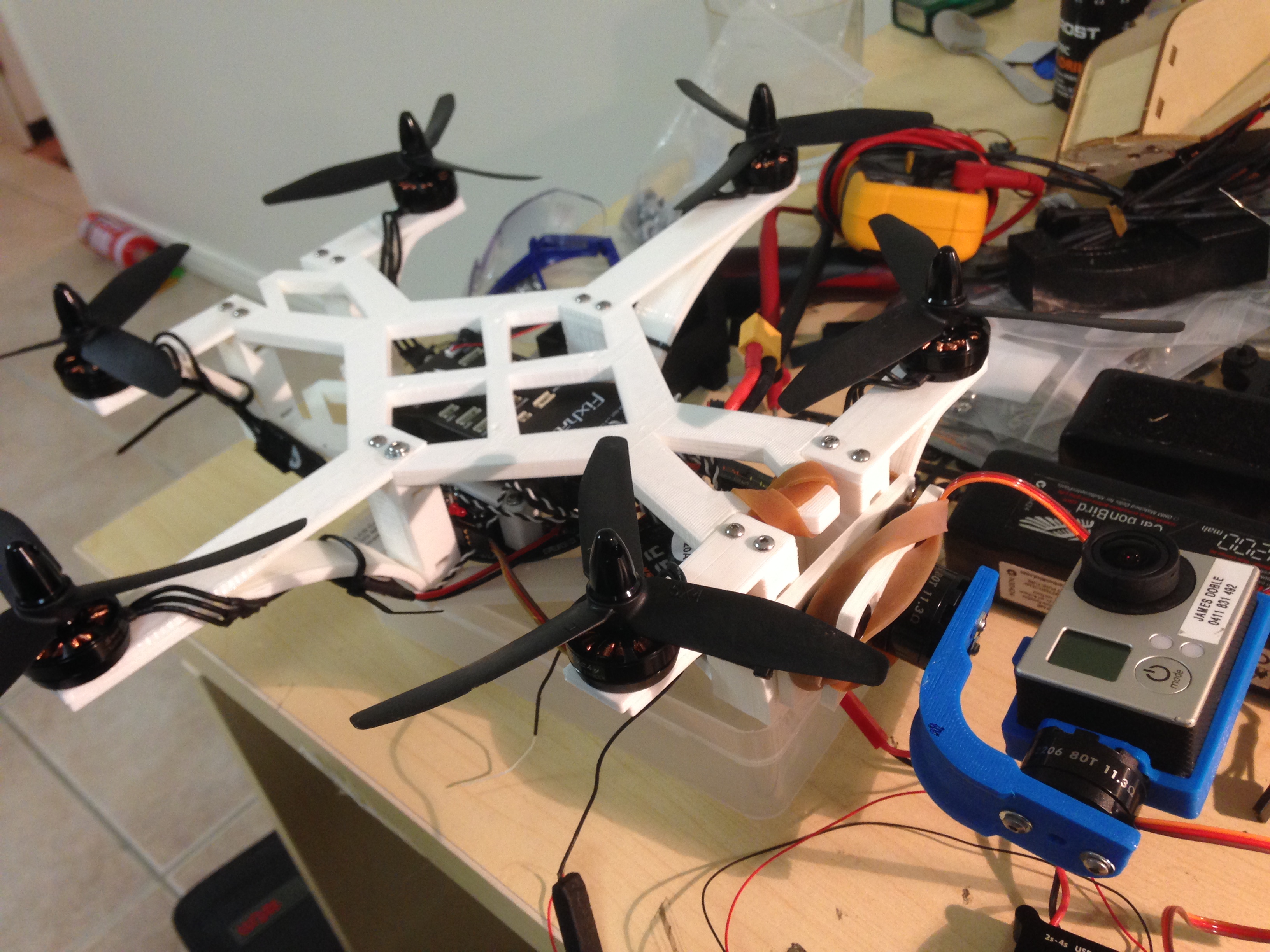
It’s AAAAAAAAAALLLLIIIIIIIIIVEEEEEEEEEEE
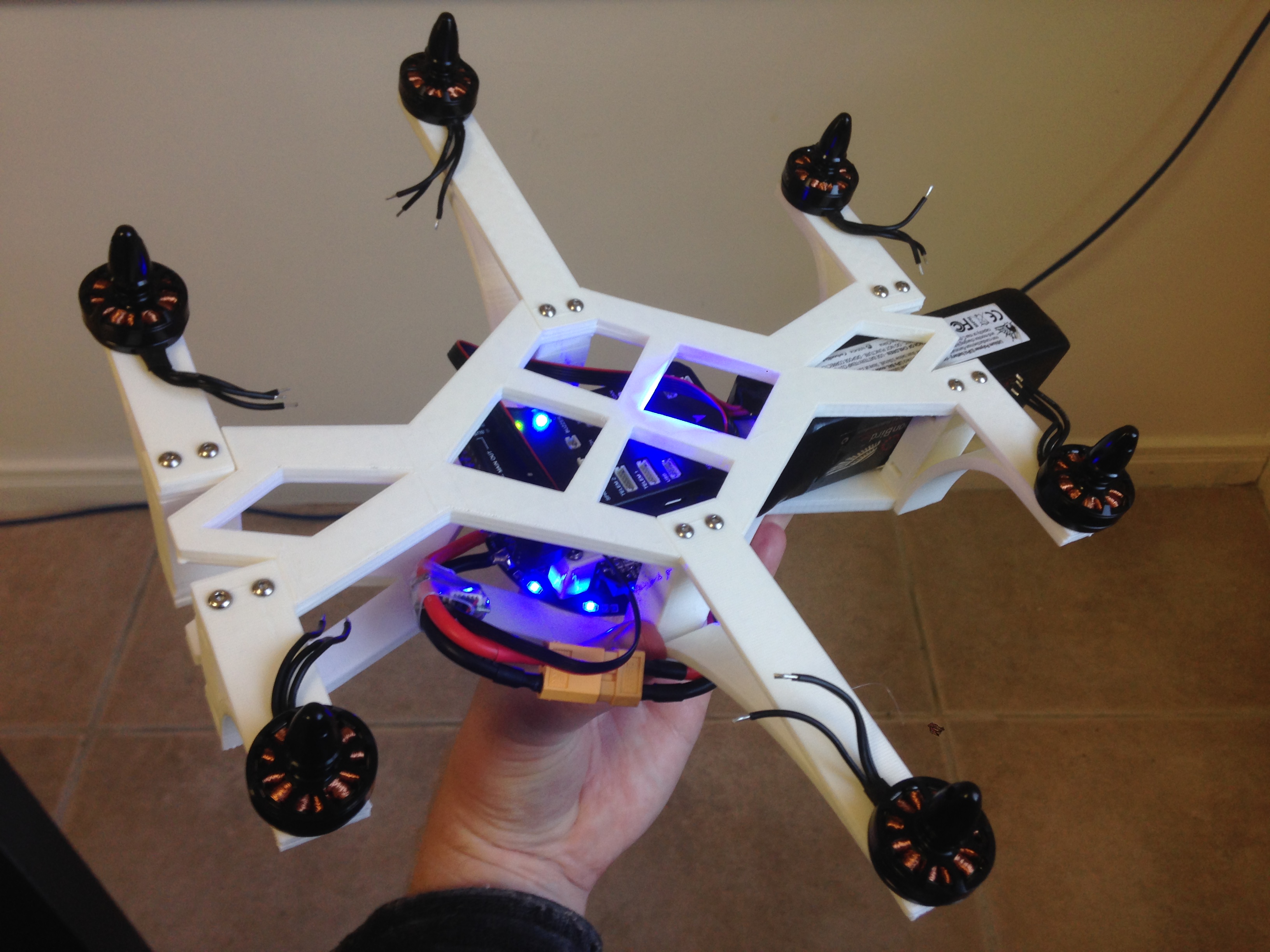
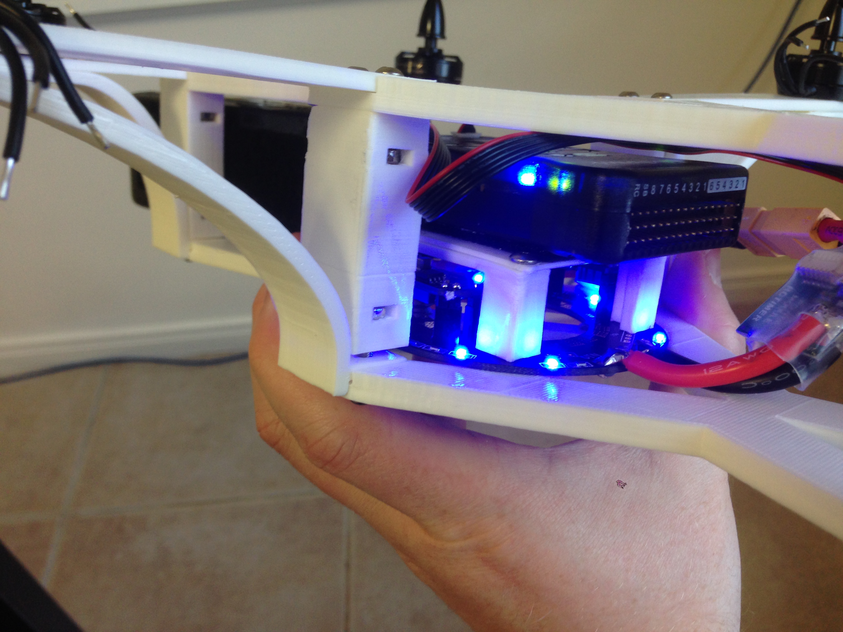
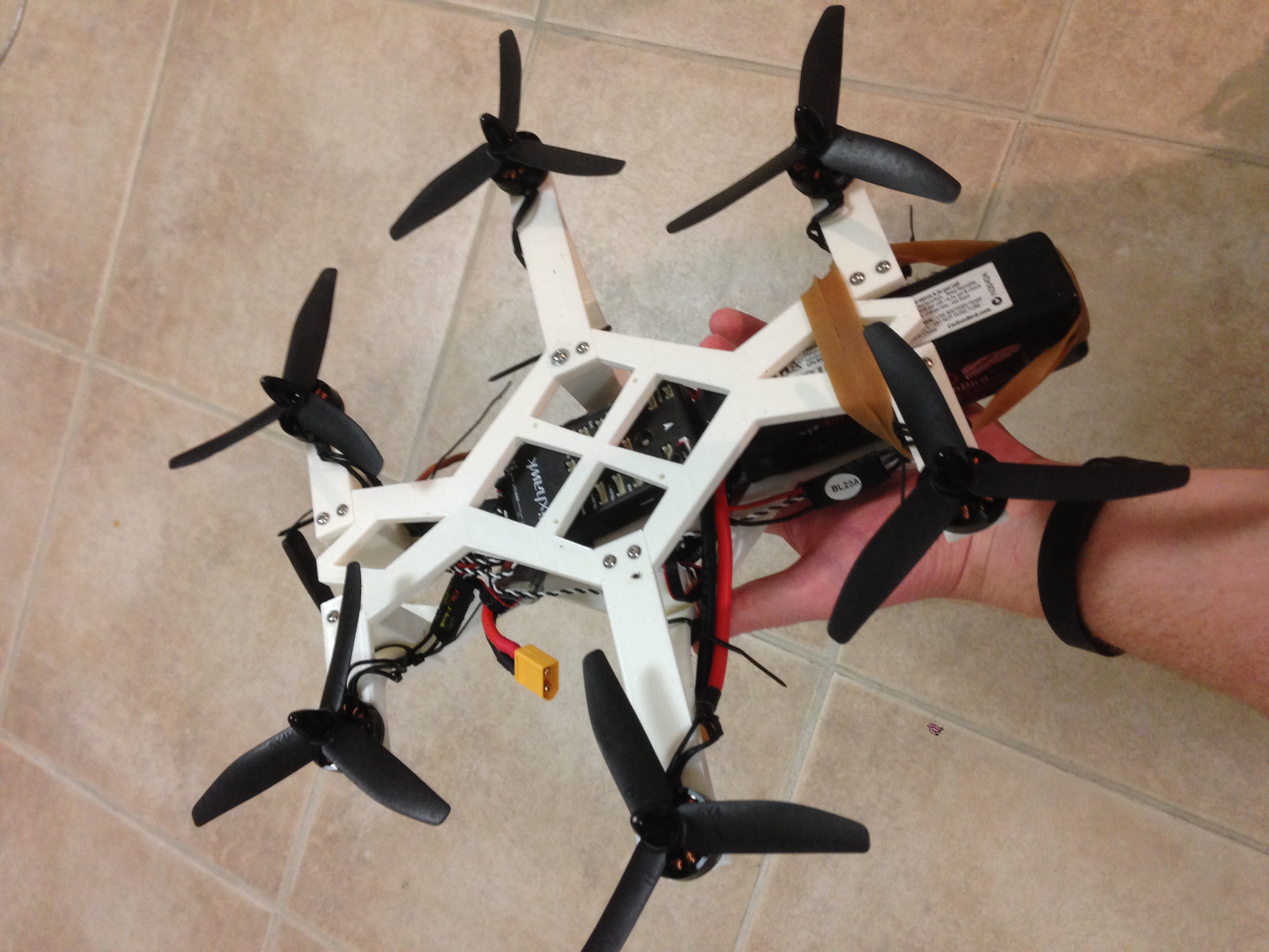
It’s a bit ghetto … but it’s ready for the first test flight!
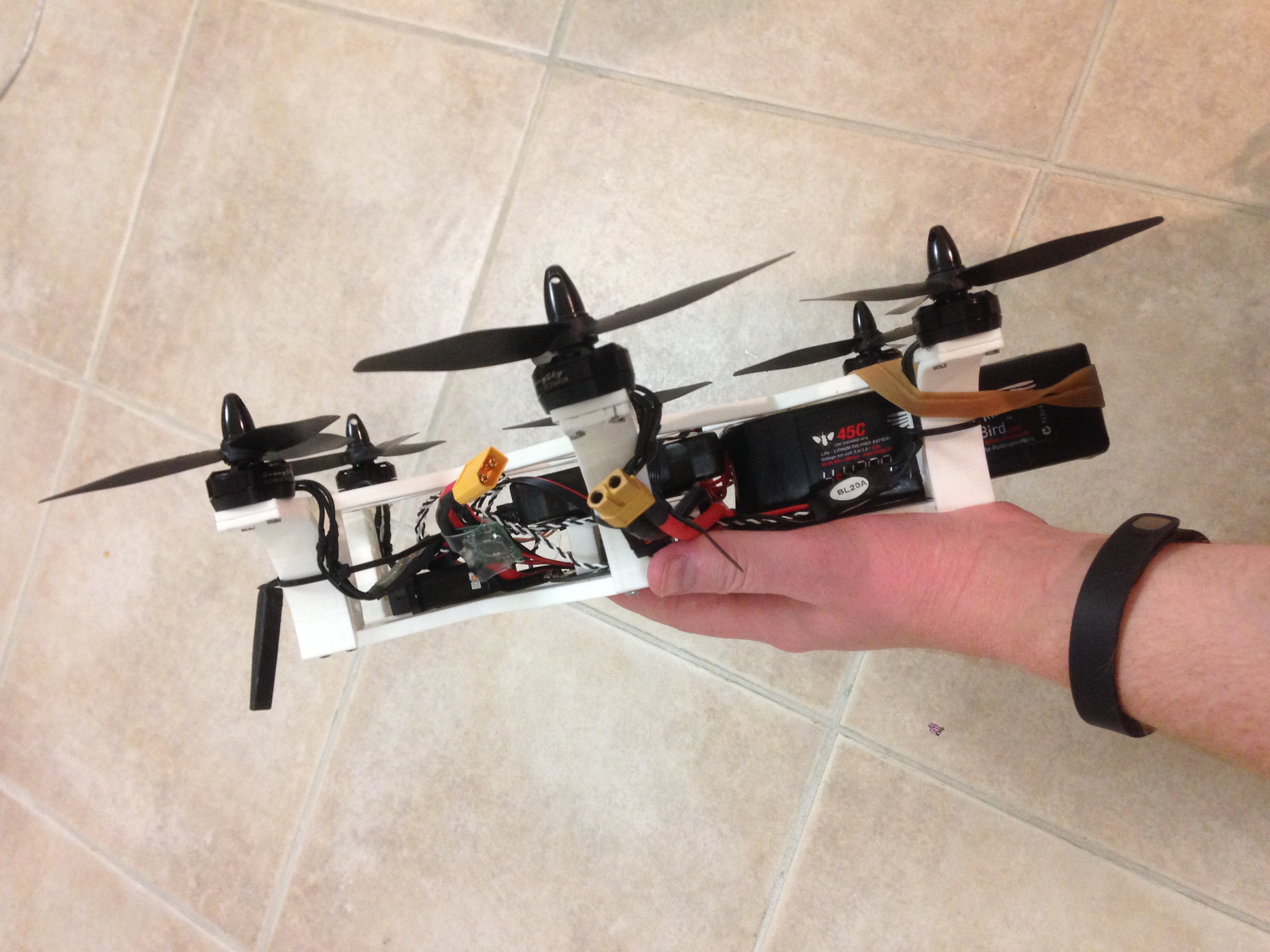
In the first test flight, I found that my center of gravity was way off. I ended up just strapping the battery to the underside of the frame. Once I did that, the craft flew very nicely. It felt great in the air and I managed a number of successful test flights. Next it was time to add the gimbal and try to get the whole thing to balance correctly.
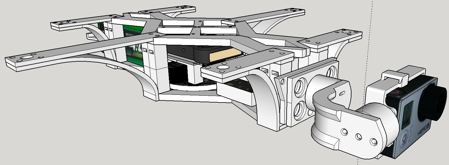
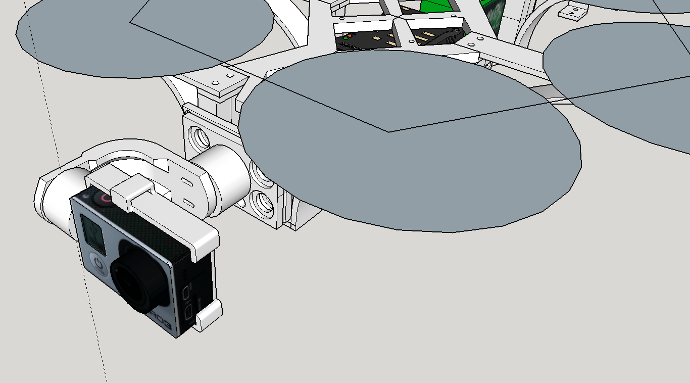
Checking that the propellers will not strike the gimbal as it rolls.
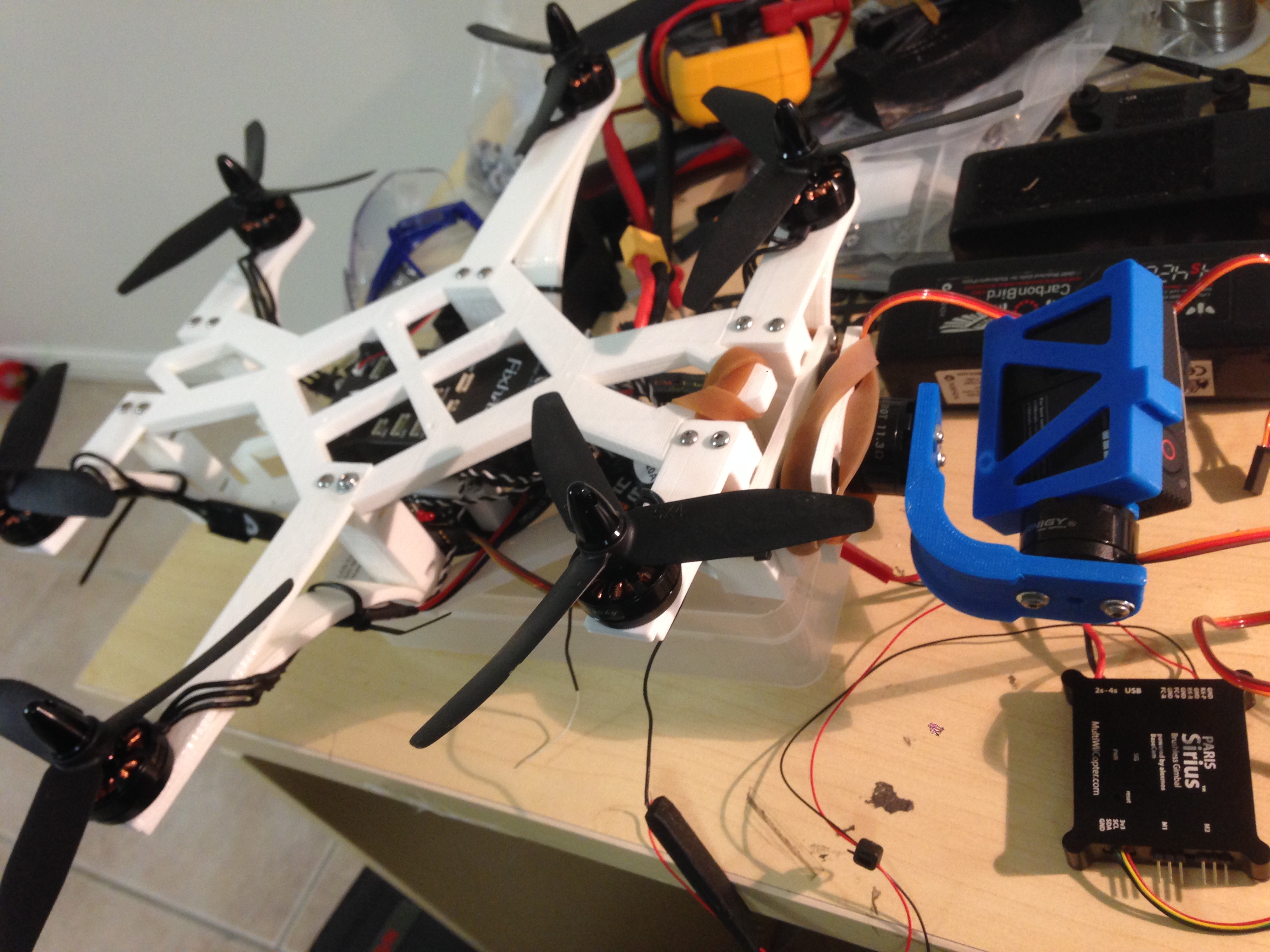
First design for mounting the gimbal to the airframe, this ended up being hopeless as the weight of the gimbal was far too much for the gello balls even with rubber bands for additional tension.
This is as far as Prototype 1 got … I managed about 5 test flights, until we had a little accident …
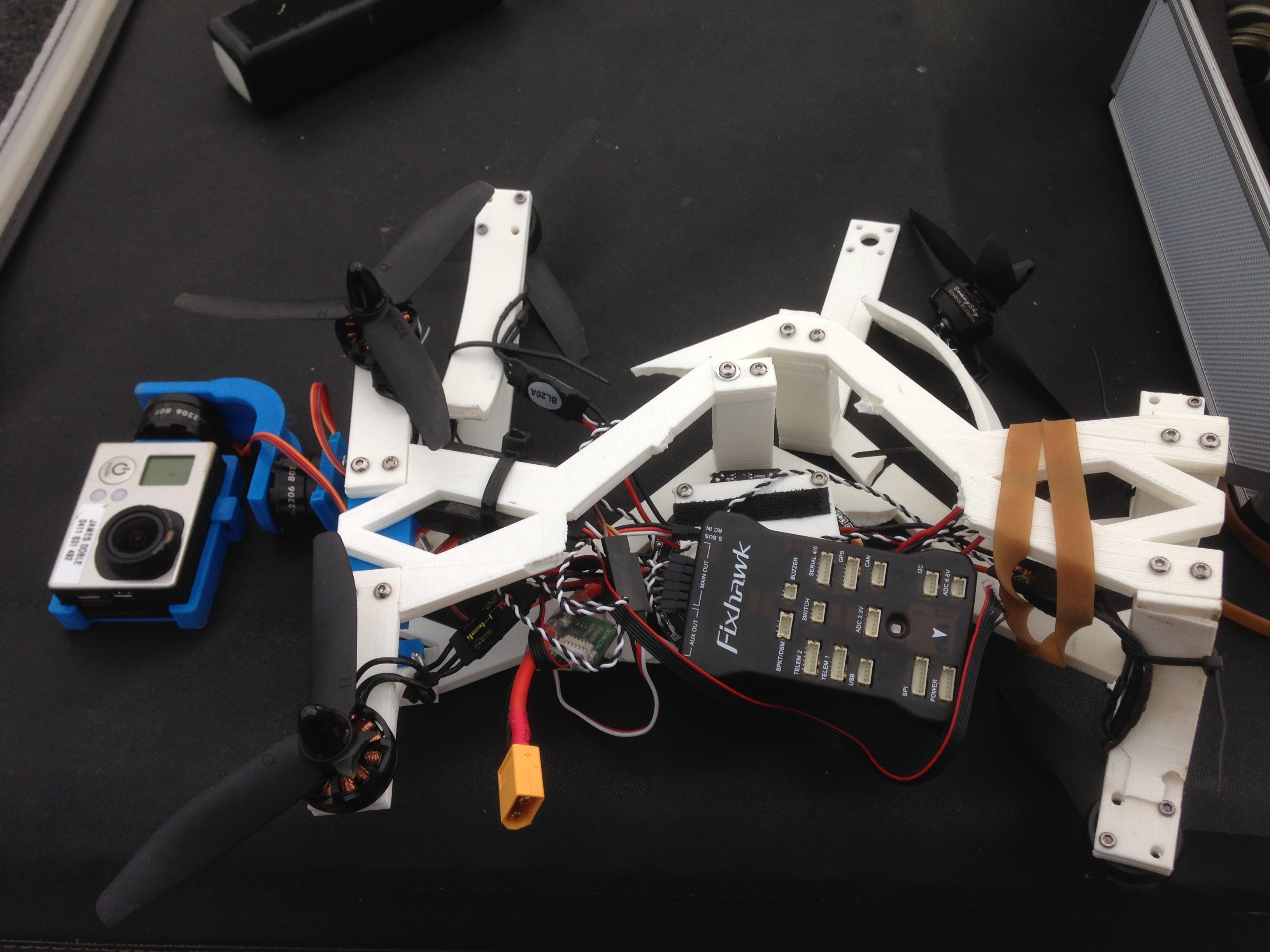

I’m uncertain what caused the crash, I think it could have been that one of the motors came free from the frame, or that one of the ESC’s failed. Regardless, it showed that the airframe was far more brittle than I thought.
While it was disappointing that the crash occurred, I was very pleased that something that I had designed and built from the ground up had worked well.
I felt like I had learned a lot from the process, and a number of design challenges that I had encountered along the way resulted in me starting afresh with a new plan.
Stay tuned, I’ll post about Prototype 2 soon!